I'm glad this thread got bumped back up. It's getting close to time to start wiring my buggy. I've been meaning to sketch out a diagram for a while. It's been a slow night at work so here's my 3:00 AM buggy wiring diagram.
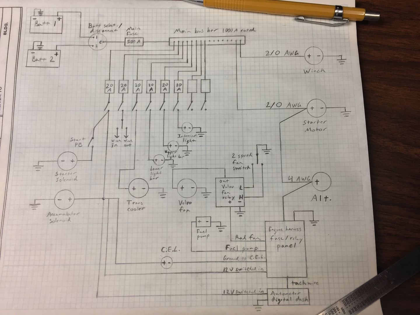
Batteries are dual Odyssey PC925s. The battery selector/disconnect is a Blue Sea 600a switch.
All battery cable will be 2/0 AWG welding cable except the charge wire will be 4 AWG. The fuel pump, radiator fan, ignition, etc. are fed by relays in the engine harness, but I'm going without relays on the rest of the loads for simplicity. I know a that's a pretty debated subject, but I'm confident it will be fine. Everything will be done with high quality components. The highest load will be the trans cooler fan at about 15a. The two light bars will be about 10a each, and the dome light probably not much more than 1a. The switch panel is a 12voltguy panel with ignition and push button start, winch controls, and 6 aux. switches.
I know it's been recommended in this thread to have the alternator charge wire on the battery side of the disconnect, and I understand why. The way I have it the alternator will still feed everything and the battery switch will really only be a disconnect, not an emergency shutdown. But the main ignition switch on my panel will drop out the relays in the engine harness for the fuel pump and the ignition system. It would be nice to have the battery switch for another emergency shutdown, but having the dual batteries made that seem to difficult to be worth it for me. I didn't want to fool with battery isolators and stuff like that. Plus the ignition switch and battery switch will be right beside each other on the console, so I guess there's really not a big advantage to having the battery switch be another shutdown.
Really my only other concern with this setup is that the engine harness gets it's constant 12V from the alternator stud through a fusible link. That's all well and good, except that when I turn off the battery switch I will lose the 12V constant for the ECU memory. I don't plan on using the battery disconnect much other than when parking the rig for extended periods. But something could always happen necessitating killing the batteries. My harness is an aftermarket standalone harness from Tilden Motorsports. I've peeled the loom back a few inches from the fuse/relay box and found where all the 12V constants are spliced onto the end of the wire going to the alternator stud. I've identified the ECU memory wire. I can cut it loose from the wire going to the alternator and run it directly to one of the batteries if necessary. I play an electrician at work, and I'm relatively confident in my ability to not butcher it up, but I just kinda cringe at the idea of hacking into a $700 harness unless it's absolutely necessary. So how big of a deal is it to have the ECU power killed by the battery disconnect that's going to remain on most of the time under normal circumstances. I know the ECU will have to relearn for a bit after having the memory power restored, but how big of a deal is that really? I know it may run a little off at first, but it should be a pretty short period of time shouldn't it? I've searched and searched trying to satisfy myself on this question, but I've never found a clear answer.
If you spot an issue, something I'm overlooking, or think I'm doing it just plain wrong speak up. I'm always open to help and constructive criticism.