-
Help Support Hardline Crawlers :
You are using an out of date browser. It may not display this or other websites correctly.
You should upgrade or use an alternative browser.
You should upgrade or use an alternative browser.
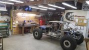
Finally....Da new rig..
- Thread starter crash2
- Start date
crash2
-Oh no I picked a side-
crash2
-Oh no I picked a side-
crash2
-Oh no I picked a side-
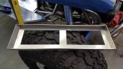
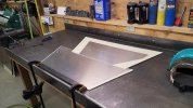
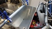
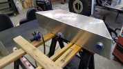
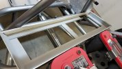
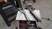
So with the lower mount/bucket done it was time to do the fuel cell and here is where I started getting nervous.. I only have like 5 hours of Tig under my belt with a high potential of fawking this up.. So of course I started with cardboard and got the front/rear aluminum pieces cut. So its roughly going to be 16 gallons. I did awful in geometry and it was many years ago to try and measure a complex shape so I kinda measured in the central points for a rectangle.
Attachments
crash2
-Oh no I picked a side-
crash2
-Oh no I picked a side-
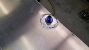
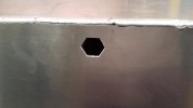
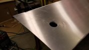
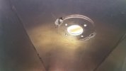
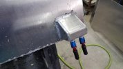
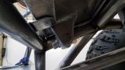
So for the cell vent I went with a typical rollover valve. Now the only issue with this type of valve is its a 2 piece so once its in and cell done you won't be able to access it. My fear was it might come loose and might not be able to tighten it so here is my fix for it. So I cut a hexagonal hole in the top of the tank that the bottom portion of the valve will sit into and then made a cap and welded it to the top of the tank. if the need ever comes the lower part will stay locked into place..
Attachments
crash2
-Oh no I picked a side-
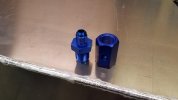
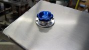
On my old cell in my toyota I had a 1/2 turn style and never really liked it. This time I went with a nice threaded style. I made a ring for the inside of the cell to give more material for the screws that secure the body of the cap for when I tapped them.
Attachments
crash2
-Oh no I picked a side-
crash2
-Oh no I picked a side-
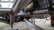
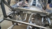
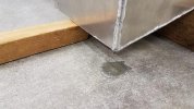
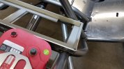
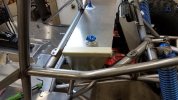
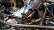
So the cell isn't done yet--still needs a suction and return and here was my plan for it. Made a drop for the bottom front edge of the cell. Once it was welded onto the cell I went and pressure checked it with air/soapy water. Not a single leak--I was pretty stoked about that.
One thing to remember about using water to leak check is the fact a water molecule is larger than that of fuel and have found no leak with water but with fuel (on my old cell for my toyota) so using air if by far the best method.
One thing to remember about using water to leak check is the fact a water molecule is larger than that of fuel and have found no leak with water but with fuel (on my old cell for my toyota) so using air if by far the best method.
Attachments
crash2
-Oh no I picked a side-
crash2
-Oh no I picked a side-
crash2
-Oh no I picked a side-
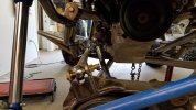
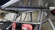
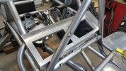
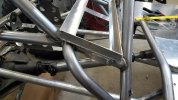
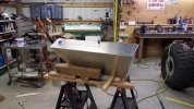
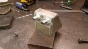
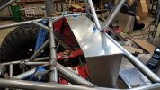
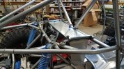
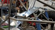
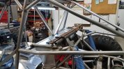
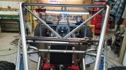
I got the upper mounts done and boy howdy they were tough. The mounts also serve a double purpose and why I built them the way I did...
Attachments
crash2
-Oh no I picked a side-
crash2
-Oh no I picked a side-
Clark
Well-Known Member
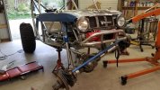
Your shop is as cool as your buggy!! Nice work on both! :awesomework:
crash2
-Oh no I picked a side-
Your shop is as cool as your buggy!! Nice work on both! :awesomework:
Thanks clark--I love my new shop--built just how I wanted it--same with the tube thingy :redneck:
crash2
-Oh no I picked a side-

crash2
-Oh no I picked a side-
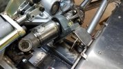
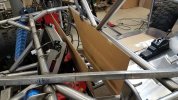
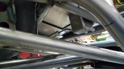
Next onto getting the front driveshaft in which meant making a mount for the pillow block. So started by measurements and tacked a mount together. My plan was to make the mount with a 3/16 spacer to give me adjustment to move the driveshaft away from the starter bolt and the tranny edge.