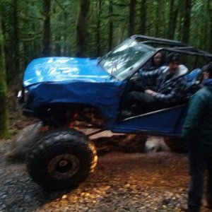
crash2
-Oh no I picked a side-
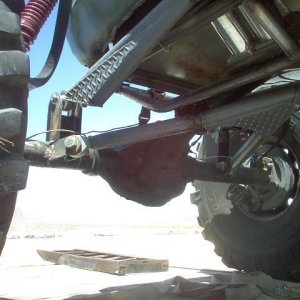
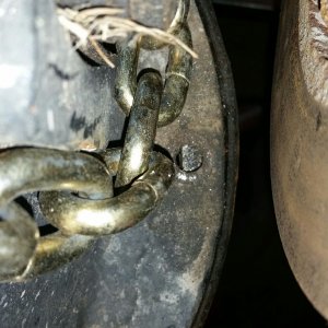
Got the gussets made/welded in and the frame rails all painted up.... Ready to drop the motor back in tomorrow..


So,Out of complete curiosity I ask why the gussets go perpendicular to the frame, as opposed to parallel with the new mounts and out to the edge of the frame?
It seems that the pulling force of the new mounts is better supported by gussets that extend out from the top of the mounts plane.
make sense?:beer:
cheers


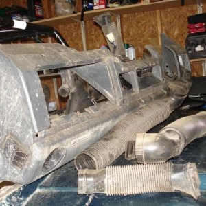
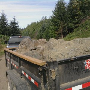
 ....no supplies means no progress lol:thumbup::thumbup::thumbup::beer: