• Help Support Hardline Crawlers :

SXOR single seater build

They go with the cluster. They perform different functions on the cluster. Programming, changing displays, clearing alarms, etc. I haven't read real deep into the manual yet. They might not all be used in my application.
 
I've been doing a few things here and there over the last few days. I got some longer bolts and mounted the battery disconnect. I also got the new shifter boot in. I enlarged the hole in the panel and made some adjustments on the linkages and got the shifters working smoothly.

I also cut a panel to fill the hole beside the seat.


I also got the radiator shroud cut and mounted the Volvo fan.


And here's the start of building the driveshafts. The yokes are Spicers, part# 3-28-777. They're 1350 yokes for 2"x.120" tubing. The four on the right are welded to short pieces of 2"x.120" to fit into the main shaft which will be 2.5"x.250" tubing. The two on the left are welded to 2.25"x.250" tubing to match the O.D. of the WOD carrier bearing stub. The mid shafts will be 2.5"x.120" tubing. I cut the tubing at work on our big vertical bandsaw to get the squarest cut I could. I heated the tubing in the oven to about 275* and pressed the yokes in then welded them up. I know they won't be perfect, but I think they'll be close enough. They're probably going to have some vibrations with the angles they'll be running at anyway.

 
You could relocate the Killswitch to the upper right of the cluster and sink a cup holder in its place if there's enough room below
 
I worked on the midship shafts today and got both of them tacked together and the carrier bearing mounts tacked in place. The carrier bearings are WOD's single ended bearings. The weld yoke is a Spicer 3-28-777 welded into a short piece of 2.25"x.250" DOM to sleeve into the 2.5"x.120" tubing. And the end yoke is a forged 32 spline 1350 yoke from Northern Drivetrain.

Starting on the rear shaft.


Here's my redneck fixture I set up to get them as square as possible and the joints in phase. I'm sure there are much better ways of doing this, but it's what I came up with and it worked pretty well for me.


All tacked together.


And tacked in place.


This picture makes it look a little closer than it really is, but it should clear the shifter linkage just fine.


Looking back from where the pinion yoke will be. As you can see this thing will see some pretty crazy angles.


Putting together the front shaft.


Mounted in place.


And looking back from the pinion again. The front shaft won't have near the angle that the rear does.


I originally planned to put short slips in these shafts hoping that would help with vibration. I already had all the parts to make the shortest slip I could find. But I mentioned it in another thread and Ryan from He-Man Machine recommend that I not put a slip in them. And since he designed and builds the bearings I figured I should definitely take his advice.
 
I started working on the 3rd members but didn't get very far. When I laid everything out I discovered that Currie shipped me the wrong outer pinion bearing. The bearing they shipped is for a 35 spline pinion but I'm using a stick 28 spline pinion. I called them up and the order sheet had the right bearing on it, somebody just grabbed the wrong one when they packed the order. The correct bearings are on the way, but won't be here until next week.

This is my first attempt at any kind of gear work, so this will be a big learning experience for me. Everybody says 9" gears are about the easiest to do though so I have that going for me. I've been reading a lot of how to articles and watching a lot of YouTube videos trying to learn.

Here's the parts list for the 3rds:

Yukon HD nodular 3.25" cases
35 spline spools
Yukon 5.13 gears
Ring gear bolt locks from ZukIzzy on Pirate
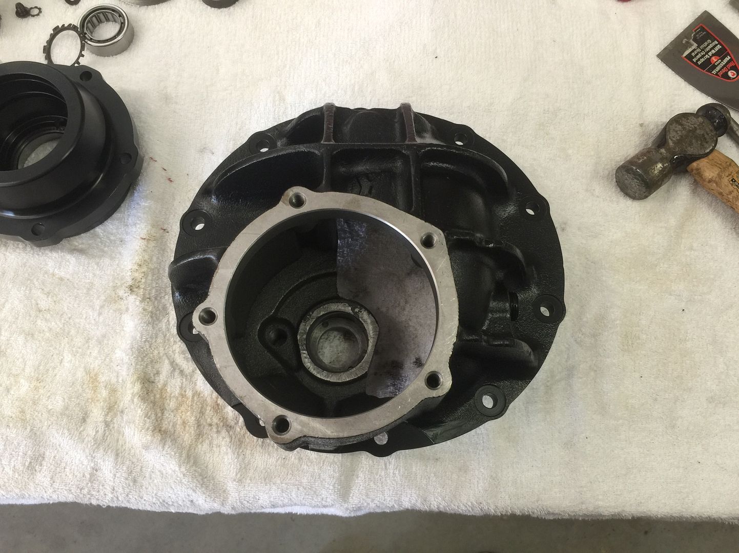
Currie big bearing "upside down" pinion supports
Trail Gear "upside down" pinion guards
Billet 1350 yokes

While I'm waiting on the bearings I went ahead and did a few things that I could get done.

I started off cleaning up the cases with acetone and got a couple good coats of paint on them.


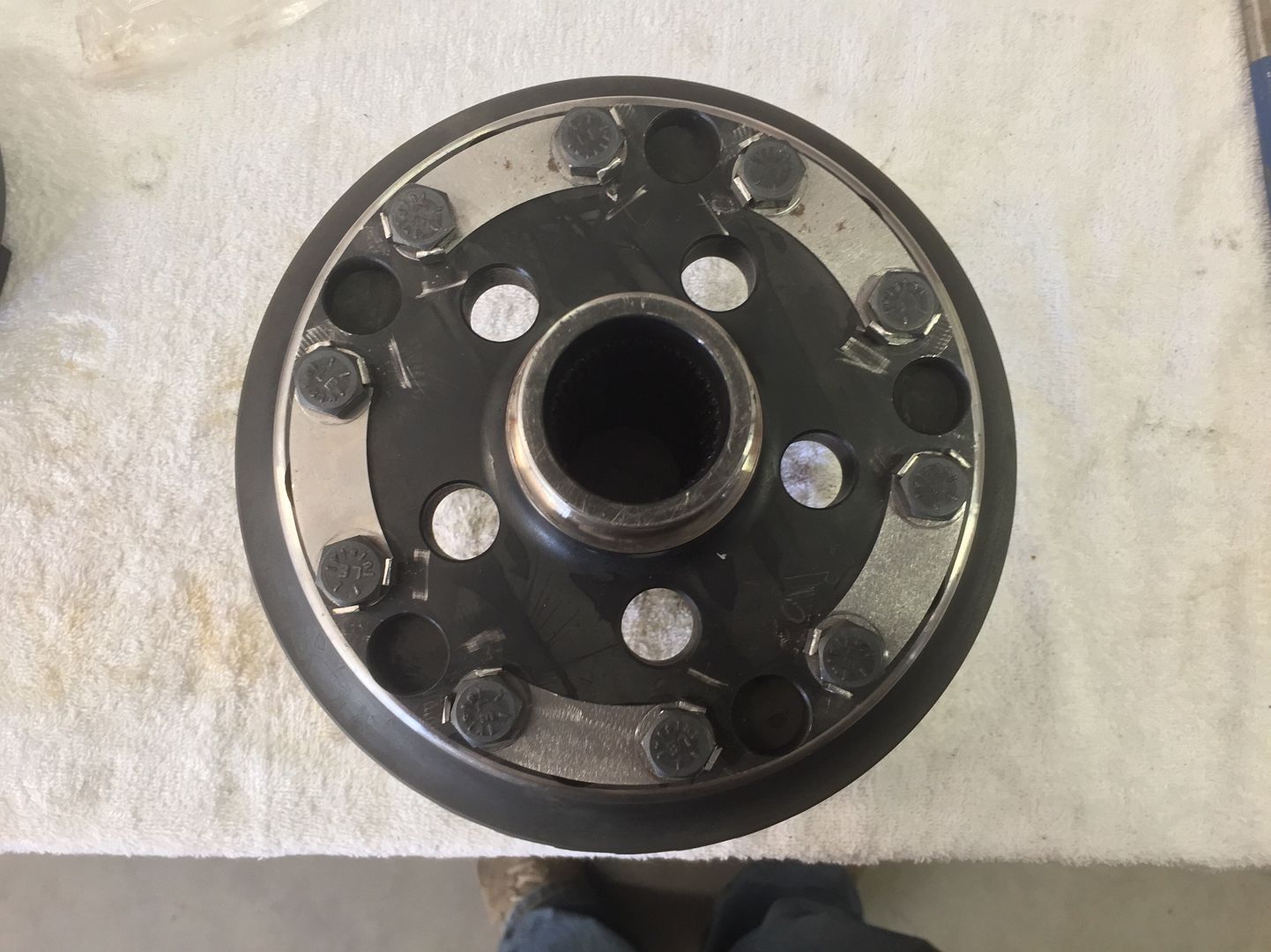
I threw one of my spare shafts in the chain vise and used it to hold the spool while I mounted and torqued the ring gear.


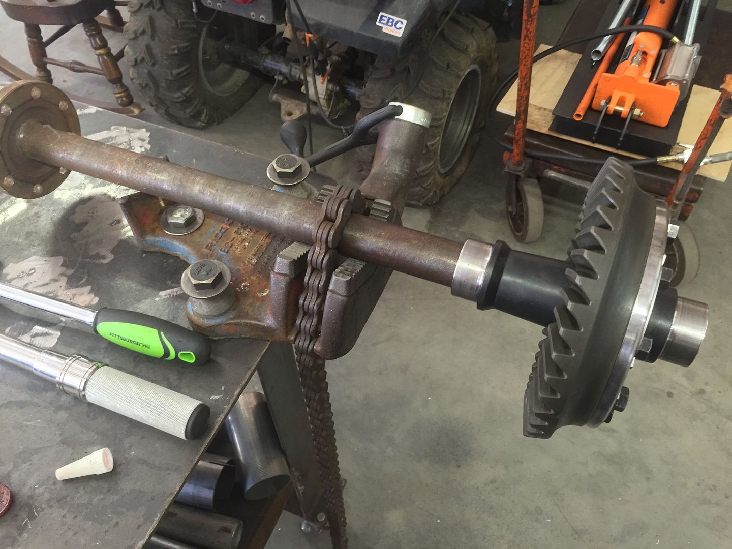
Here you can see the ring gear bolt locks.


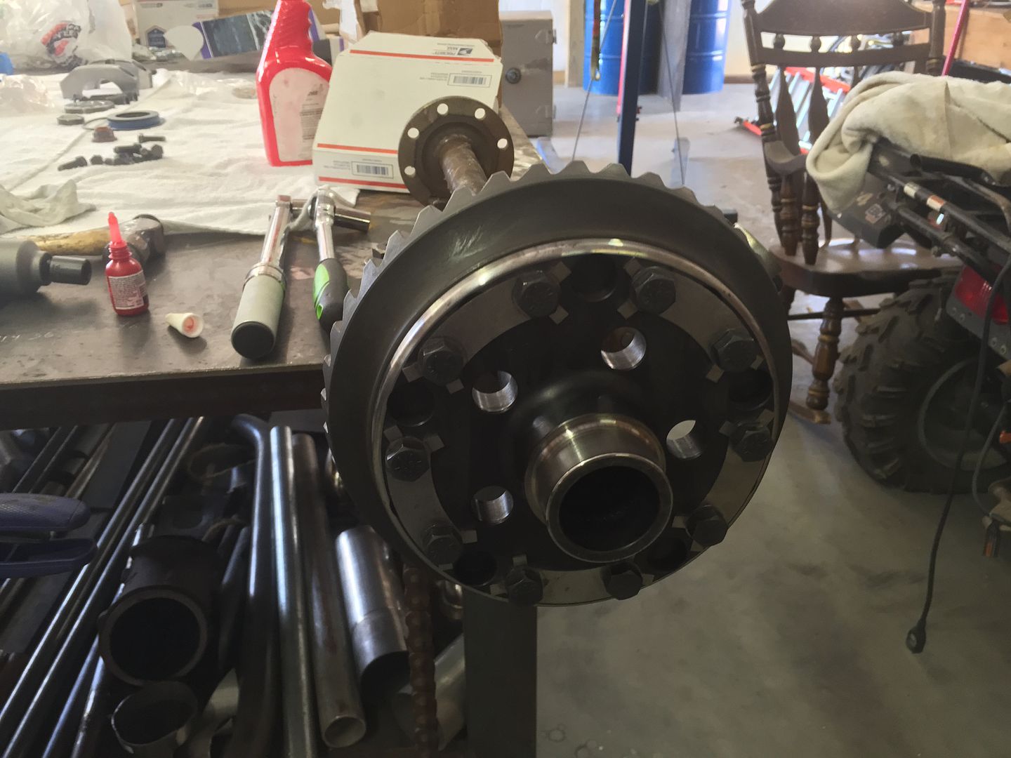
And here with the tabs bent up to keep the bolts from backing out. The bolts are also torqued with red loctite.


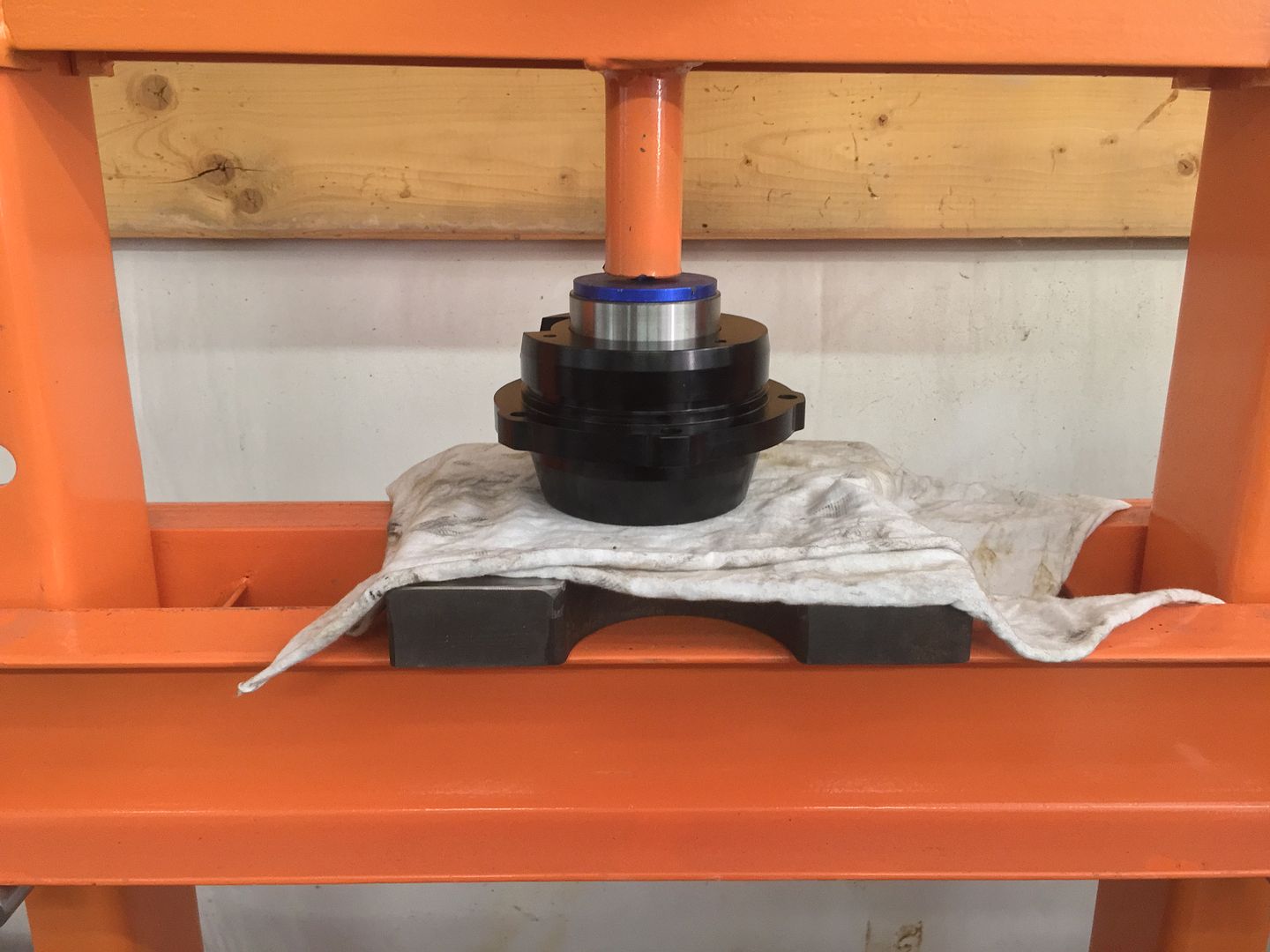
Went ahead and pressed the inner pinion bearing race in.


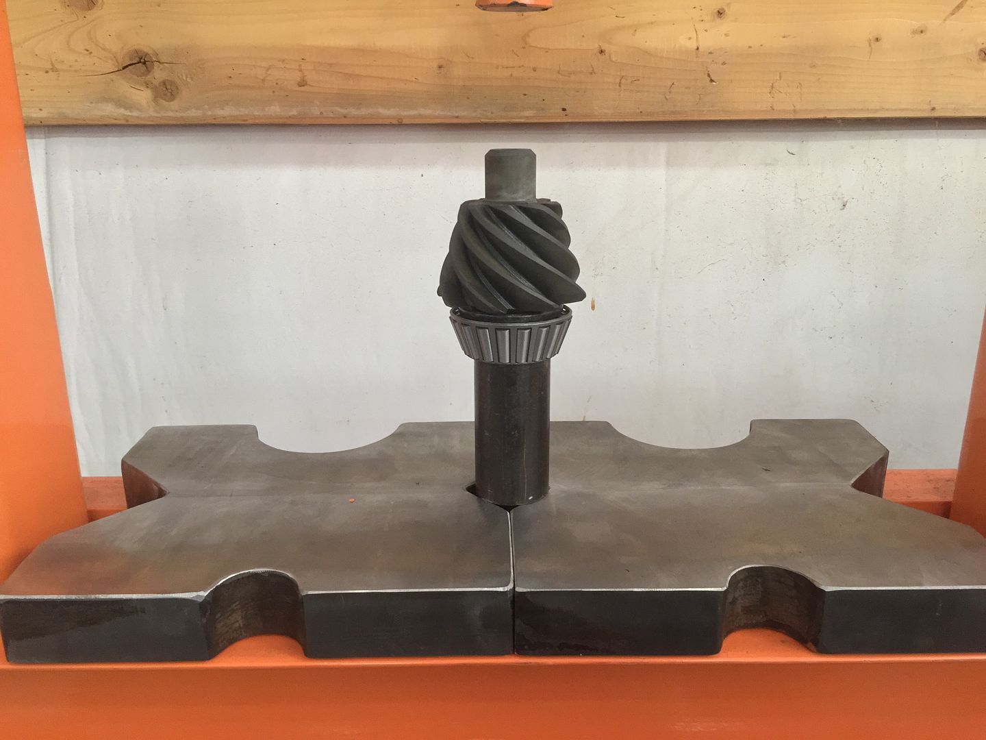
And pressed the inner bearing on the pinion.


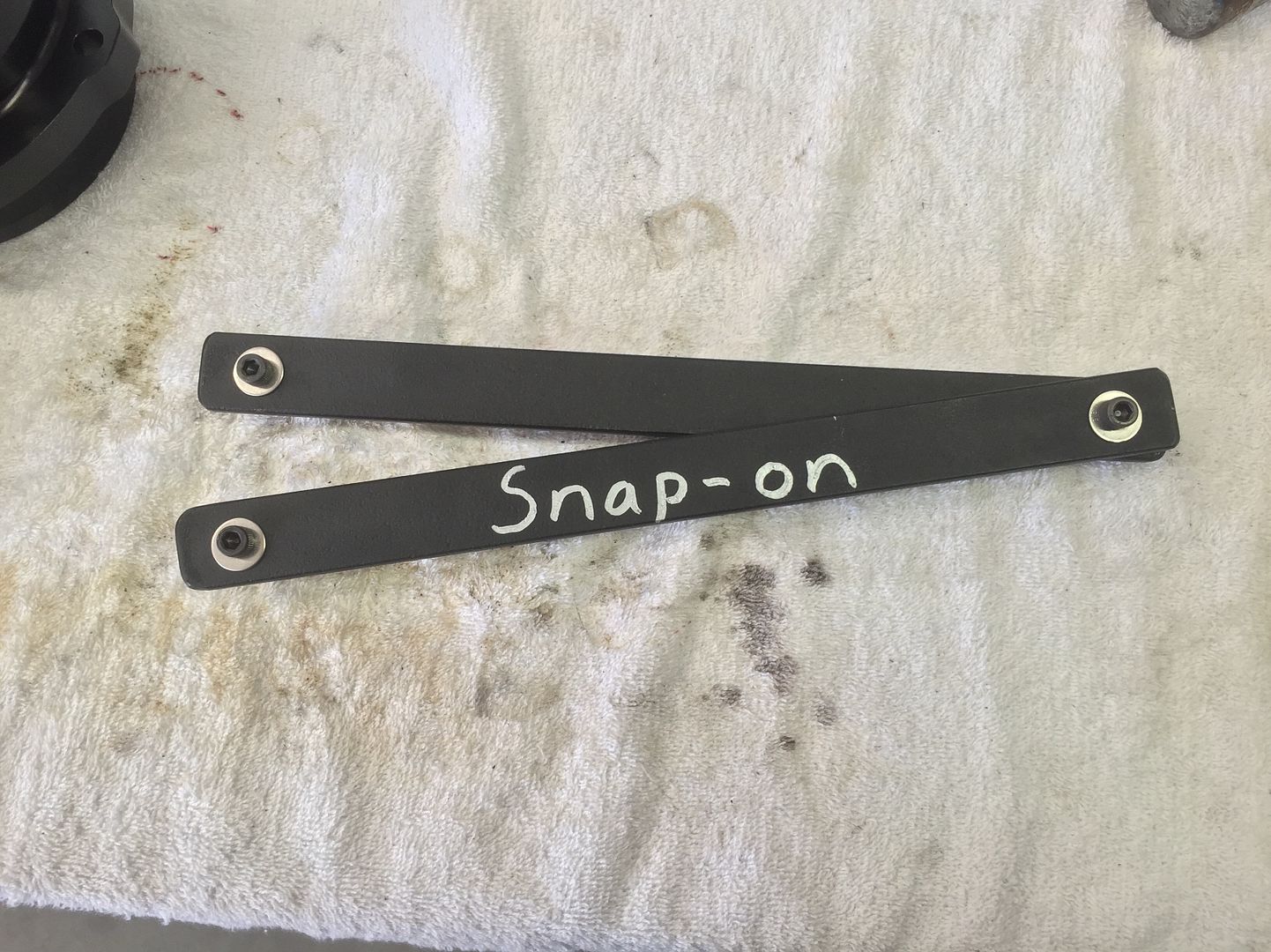
And here's my high dollar spanner wrench for the side adjuster nuts. Lol.


That's about all I got done. I could have started on the other 3rd but I didn't want to get parts mixed up between the two so I figured it would be best to just wait.
 
I finished up one 3rd member today. It took a few hours and several attempts but I ended up with a pattern that I'm pleased with. When I started the build I planned to just pay someone else to set up the gears, but I'm glad now that I took the time to learn and do it myself. It's really not that bad at all.

Here's the final gear pattern. The backlash is at just over .010" with a pinion shim height of .019".


And the completed 3rd member.


I still have one more to do. Hopefully I can get at least started on it before I have to go in to work tomorrow night.
 
The fact that the backlash was a little out of spec was bugging me so I made some adjustments today and got the backlash down to .009".


But a few of the ring gear teeth just barely drag on the pinion pilot bearing housing now. Here you can see where it's dragging on the toe of the ring gear.


I checked the backlash in several spots and it's consistent so I don't think runout is an issue. It doesn't lock it down and I can still easily turn the yoke by hand. You can just feel it barely drag as the teeth rub. As bad as I hate to I'm going to tear it back apart.

I've been doing some reading and I guess this is a pretty common problem. Wish I would have found that information before I started, oh well I guess I'll just chalk this up as a learning experience. I think rather than grind more on the pilot bearing housing I'm just going to pull the ring gear back out and grind the toe down just a little. From everything I've read that seems like the best solution.

One step forward, two steps back... Oh well.
 
I didn't really take many pics but I tore the 3rd back apart today and ground the ring gear toe down just a bit. I went ahead and did the ring gear for the other 3rd as well.


I got the first one put back together. The ring gear clears good now, and the backlash and pattern both look good. I also got the other 3rd set up today but I didn't take any pics of it. It looks identical to the first one though.
 
I finally had a few hours free to work on this thing a bit today. I finished up the chassis side of the brake lines. The hard lines are .25" 316 stainless seamless tubing. The fittings are Swagelok compression fittings. And the flex hoses are Swagelok teflon lined braided stainless with .25" tubing ends. I also added a valve in the rear brake line to use as a parking brake if needed. I'm also going to split some rubber hose to go over the tubing and flex hoses anywhere there's any rubbing.


Top