• Help Support Hardline Crawlers :

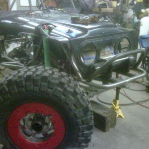
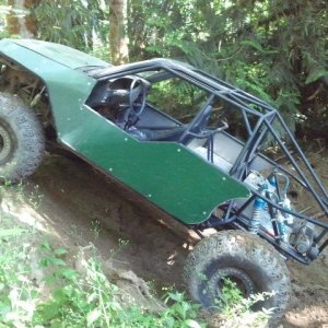
So i bought a 51 Whilly

MAP, 5V in, .1V out only raises to 2.5V max? should be 1V to 4.5V:
What's the voltage with key on engine off?


TPS, 5V in. 0.25V out ad idle and 2.5V at WOT? should be 1.2V 4.5V:
Even though these are technically non adjustable TPS' I would bend the tab and make it .54 volts at idle. At that point it SHOULD be close to 5 volts WOT but probably a little lower. Are these voltages taken with a scan tool or volt meter? If volt meter make sure you're using the correct two wires.
I bet getting the TPS into spec will make it run much better.:awesomework:
 
Voltage taken with both scan tool and my meter by back probing the blue wire.

the scan tool gives operating data real time.

so i dont think its the TPS giving incorrect voltage i believe the wire is being drained of voltage somewhere. if i take my TPS and put it into another vehicle it reads exactly like it should.

so does the MAP.

next im gonne check continuity on the signal wires and verufy they go to the correct pins. i need a magnifying glass to read those damn little numbers.

i have a bunch of sensors and stuff to swap out and have verified all are good on the test vehicle.:D

maybe run two separate signal wires outside the harness?

anyone have two 35 spline 60 rear axel shafts 34" long so i could drive it?

tax return should cover axels and drive flanges:awesomework: maybe file this week.
 
Voltage taken with both scan tool and my meter by back probing the blue wire.

the scan tool gives operating data real time.

so i dont think its the TPS giving incorrect voltage i believe the wire is being drained of voltage somewhere. if i take my TPS and put it into another vehicle it reads exactly like it should.

so does the MAP.

next im gonne check continuity on the signal wires and verufy they go to the correct pins. i need a magnifying glass to read those damn little numbers. :redneck::redneck::redneck:

i have a bunch of sensors and stuff to swap out and have verified all are good on the test vehicle.:D

maybe run two separate signal wires outside the harness?

anyone have two 35 spline 60 rear axel shafts 34" long so i could drive it?

tax return should cover axels and drive flanges:awesomework: maybe file this week.

Fixed!!! :haha:
something just dawned on me....inside the ECM they use pull-down resisitors for the signal side, and is it possible by tying the TPS/MAP 5V ref together, the resisitors are pulling your voltage down? Or did you pull the voltage from the signal wire, and not the constant 5V wire????
 
Fixed!!! :haha:
something just dawned on me....inside the ECM they use pull-down resisitors for the signal side, and is it possible by tying the TPS/MAP 5V ref together, the resisitors are pulling your voltage down? Or did you pull the voltage from the signal wire, and not the constant 5V wire????


with connector disconnected the ref voltage it 5 V. once you plug it in it drops, so not plugged in it provides 5 V once plugged in it has less volts when back probing to like 2.5V.

i spliced the Map ref voltage 5V wire into the TPS ref voltage 5V wire.

in both cases they measure 5 volts unplugged and 2.5V plugged in.
 
Are you SURE your tapping the 5V ref wires, and not the signal return wires??? Unplugged, they will read 5V...with it all plugged in, test for any of the other wires having 5V....either that, or the ECM pin they are being supplied from is not actually a 5V ref, but a signal return rather...
 
Are you SURE your tapping the 5V ref wires, and not the signal return wires??? Unplugged, they will read 5V...with it all plugged in, test for any of the other wires having 5V....either that, or the ECM pin they are being supplied from is not actually a 5V ref, but a signal return rather...


yes positive.
 
so i worked on other things to relieve my frustration. then sunday i looked at it again. this is what i found doing a pin by pin readout on the ECU end:

Blue connector has:
PIN F-14 should be a White 5V reference and it actually has a pink wire?
pin F-13 should have DK Blu VSS Buffer it actually has grey wire?
Pin E-3 Should be empty and has dark green wire?
Pin E-12 should have DK Grn A/C request and is empty?


Red connector has:

Pin A-9 should be Dk Grn injector 12V and is empty?
Pin B-9 should be empty and has a tan wire?

ill be calling the harness people monday morning.:booo:
 
Hang in there hip! ya can almost see the light at the end of the tunnel! i have some spare Dana70 shafts maybe there not too long? ill messure em when i get to the garage later today.
 
i moved the two wires down to what the diagram said they should be and **** runs great now.:cheer::awesomework::cool::beer::redneck:

im out of time in the shop today so tomorrow ill start over at base timing and reset everything.

then finnish installing the engine cover and hood.
 
It's always gratifying when you sit down and take some time to figure it all out! Glad you got it!:cheer: Even though sometimes it can and will drive ya up a wall (not in the buggy either:haha:)!!! Well, now ya can drive up a wall! :awesomework:
 
i moved the two wires down to what the diagram said they should be and **** runs great now.:cheer::awesomework::cool::beer::redneck:

im out of time in the shop today so tomorrow ill start over at base timing and reset everything.

then finnish installing the engine cover and hood.

Glad you found the problem Hip!!!!!:cheer::awesomework::beer:
 
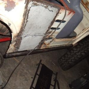
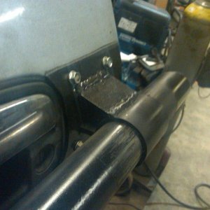
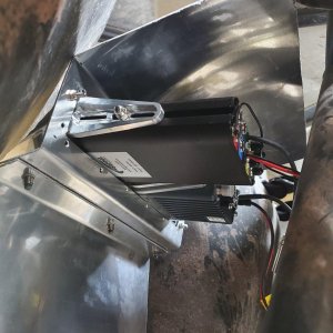
new progress.
 

Attachments

  • P1010619.JPG
    P1010619.JPG
    86.7 KB · Views: 310
  • P1010620.JPG
    P1010620.JPG
    86.4 KB · Views: 358
  • P1010621.JPG
    P1010621.JPG
    88 KB · Views: 315
  • P1010622.JPG
    P1010622.JPG
    87.1 KB · Views: 319
so i had a good three days working out little bugs.

i vented the engine coolant and now my fan switch works on high but not low?

ordered some intake hose and tube.

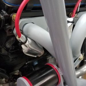
redid a portion of my exhaust, moved it away from my oil pan a little, moved it down as it was touchig my floorboard under the passenger seat, and was very close to my bottom link johnnie joint. much better now:awesomework:

re-routed some steering hoses so wiring does not touch them.

got that all done and let the motor run for an hour or so, no leaks anywhere....:D

then i noticed my gauges stopped working, all of em.:eeek:

THEN I RIPPED ALL THE DASHBOARD WIRES OUT.:awesomework:
 
Last edited:
Top