You are using an out of date browser. It may not display this or other websites correctly.
You should upgrade or use an alternative browser.
You should upgrade or use an alternative browser.
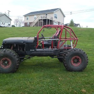
Anyone here with a 2JZ-GTE vvti swap?
- Thread starter Waffle
- Start date
I'm going to call TweakdPerformance about their fuel pump controller. The OEM used a seperate Fuel Pump ECU to control output and at two different speeds, but Tweakd seems to have a simple/cheap/reliable controller that'll engage the pump circuit only when the engine is running/cranking and shuts off if the engine shuts off.
Here's a link to the info. It's really old so we'll see what they say. Just putting it here since it's overall function is important.

 www.supraforums.com
Here's a link to the info. It's really old so we'll see what they say. Just putting it here since it's overall function is important.
Controlling fuel pump with 2JZ ECU - Fixed once and for all
Hi guys, hope you've all been well. Sorry I've been MIA, we have been slammed here at the shop and I've had too much on my to-do list to drop by the forums very much. As many of you know the 2JZ ECU does not have a circuit to switch on the circuit opening (fuel pump) relay as it uses a separate...
Here's my source for ip67/ip68 waterproof power distribution modules. This 2JZ swap will probably get the GEP 24. I myself have 2 in my bug. A Littelfuse 18 for accessory circuits (soon to be GEP 48) and a GEP 3 iso relay module controlling both speeds of my Volvo fan using the LS ground switching outputs.
This is a great company for wiring stuff.
This is a great company for wiring stuff.
I called Tweakd and they said their fuel pump controller isn't compatible with the vvti motors, so this will get a Walbro style pump and the relay will be triggered by the ignition switch while in the run and crank position. I'll have to compare the 2JZ fuel pump pressure with the Walbro pressure/amperage curve chart, but I'm fairly certain I can use a 20a relay to switch it, which means I can indeed use the GEP 24 position box for everything.
Update: looks like the Walbro GS341 "255" is commonly used. In this app at 13.5v it'll use just 8amps at 43psi. So I'll be using a 20a 280 relay, 15a fuse and 10ga GXL wiring back to the pump to keep voltage loss at a minimum.
Update: looks like the Walbro GS341 "255" is commonly used. In this app at 13.5v it'll use just 8amps at 43psi. So I'll be using a 20a 280 relay, 15a fuse and 10ga GXL wiring back to the pump to keep voltage loss at a minimum.
Last edited:
He already has an Eaton 15305-2 fuse/relay box. I have a love/hate relationship with this version since it's bussed but lacks terminal position locks, but we're probably going to go with it.
The fuse side is bussed which is a plus. The relay side is bussed too but it's at pin 86 (coil +). To compensate I'm going to flip the relays upside down so that pin 85 (coil -) is bussed and we can utilize positive switching, then I'll remove/black out all the identification marks so it doesn't appear upside down or cause confusion later down the road.

The fuse side is bussed which is a plus. The relay side is bussed too but it's at pin 86 (coil +). To compensate I'm going to flip the relays upside down so that pin 85 (coil -) is bussed and we can utilize positive switching, then I'll remove/black out all the identification marks so it doesn't appear upside down or cause confusion later down the road.
ridered3
Not Rigless
Did y'all get this thing wired up?
I was just over there today actually. I've been busy looking for a new job and he's been busy with everything.Did y'all get this thing wired up?
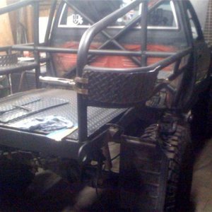
Despite me getting anxiety attacks everytime I look at the engine bay, I did manage to start on the PDM and finish the main circuits. There's still a few wires left on the body harness that'll need configured, but progress was made even if it was slow.
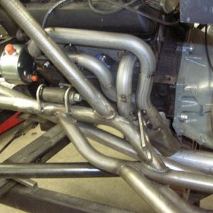
He was busy doing final installation of a new clutch to match the 2JZ to a new bellhousing with 23spl r151f dual cases. He's also having to deal with moving his 3rd link over to the drivers side to make room for the exhaust on the passenger side. Doing that meant moving the trackbar bracket forward.
PS: most of the wires you see here are either looped back into itself thru the body harness, or they're automatic transmission wires which will be
de-pinned here soon.
This isn't the way I would have done things, but that's always easier to say in hindsight. And then there's the fact that it's not mine. But, he's a friend and if I can help make it happen then I'll at least try.
Here's a closeup of the wiring "area". The white multiplug on the right side is the Aristo body harness, the #1 source of my anxiety. This all tucks inside an Aristo ECU box and has a cover to help seal out the elements. It looks a mess now but you should have seen it b4. Gettin there!
Next is waiting for the second PDM bracket so I can actually mount it, fuel pump circuit, starter circuit, tying into the ignition switch.
Markrobinson
Well-Known Member
- Joined
- Aug 13, 2010
- Messages
- 702
This
This gives me hopeThis isn't the way I would have done things, but that's always easier to say in hindsight. And then there's the fact that it's not mine. But, he's a friend and if I can help make it happen then I'll at least try.
Here's a closeup of the wiring "area". The white multiplug on the right side is the Aristo body harness, the #1 source of my anxiety. This all tucks inside an Aristo ECU box and has a cover to help seal out the elements. It looks a mess now but you should have seen it b4. Gettin there!
Next is waiting for the second PDM bracket so I can actually mount it, fuel pump circuit, starter circuit, tying into the ignition switch.
View attachment 148965
I'm planning an equally stupid swap of a newer Nissan engine into an older Nissan. Probably going to have a Tupperware of wadded up wires and ecu under the dash.
Had a chance finally to spend some more time on it. I'll post up each step to avoid any confusion.
The ECU pin routing is done (I think) and we've moved onto the Aristo body plug side that needs work. First step is locating this BF1 plug. You'll connect pin 7 directly to a 5a fuse to supply constant power to the alternator battery voltage sense circuit.

The ECU pin routing is done (I think) and we've moved onto the Aristo body plug side that needs work. First step is locating this BF1 plug. You'll connect pin 7 directly to a 5a fuse to supply constant power to the alternator battery voltage sense circuit.
Last edited:
This next plug and pin routing is a bit tricky because the sources don't specify certain details that I'd deem critical. Let me explain.....
Locate this BF2 plug on the Aristo body harness side. You'll be using 4 pins from this one. #6,#7,#8,#9.
#9 is main efi relay switched power input which connects to the main efi relay output to power up the ECU, VSV and other stuff. This meant I had to cut and tie into the EFI relay #1 that I had already wired up. No big deal, but it's something to watch out for.
Pin 6 and 7 is what had me stop for a bit because of what the sources say with connections and how it's worded.
Pin 6 is an input for 12v+ power to coils and igniter. Pin 7 is an input for 12v+ power to injectors. This source says to connect both pins to battery voltage via the ignition switch when in the run/crank position, but no mention of relays or fuses. Ha, imagine that! However, I'm using my LS experience to say these two should actually be switched on by an efi relay, and since I have 2 efi relays in this swap and already pigtailed into #1, I chose to pigtail the EFI relay #2 to power these. It makes sense to me at least. I don't know the total amp draw on this circuit which makes me really nervous.

Pin 6 is an input for 12v+ power to coils and igniter. Pin 7 is an input for 12v+ power to injectors. This source says to connect both pins to battery voltage via the ignition switch when in the run/crank position, but no mention of relays or fuses. Ha, imagine that! However, I'm using my LS experience to say these two should actually be switched on by an efi relay, and since I have 2 efi relays in this swap and already pigtailed into #1, I chose to pigtail the EFI relay #2 to power these. It makes sense to me at least. I don't know the total amp draw on this circuit which makes me really nervous.
Last edited:
There are other things I need to spend time on and verify their need in a manual transmission application like this, so it's possible I may have to revisit a plug for things like neutral safety switch pin, diagnostic pins, tach, etc etc. From what I can tell nearly all of the wires left are auto trans pins that I can remove entirely.

Things are moving along. The Holley intercooler & Spal fan will get mounted soon. Water neck inlet was cut/spun/welded to 8 o'clock so coolant can flow down the passenger side in both directions. Intercooler and intake plumbing is getting done soon too by a pro that can tig elbows. Throttle cable was modified and it works. It now has a belt to fit with AC delete and HO steering pump with big pulley.
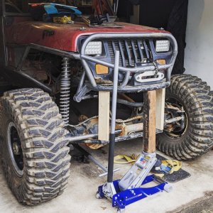
Currently relocating the battery out back and drawing up plans for radiator and fuel cell fitment. 3-link is almost done and the oil pan baffles should arrive soon.

Currently relocating the battery out back and drawing up plans for radiator and fuel cell fitment. 3-link is almost done and the oil pan baffles should arrive soon.