• Help Support Hardline Crawlers :

Brainwashed

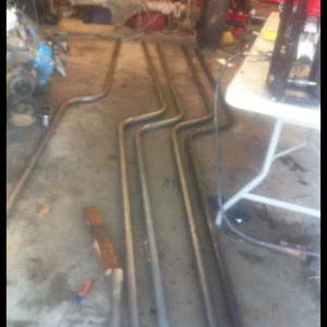
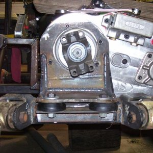
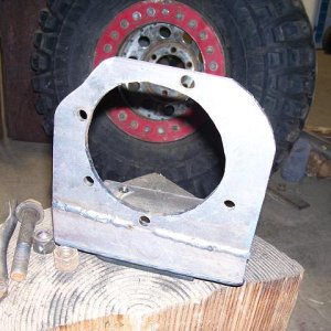
My process for doing a chassis--and one I have a number times(and seems to work for me). I always start at the skip plate. Start by figuring the width of the chassis and then lower link placement on the chassis. Once I get that figured out I rough in the side plates. My next step is to build the lower links. Once thats done I now have the length of my uppers since I like to run equal length links. So once I have the upper lengths I can figure out the multiple location holes for the uppers. Since this is my first MOA I wanted some diversity on the upper placement for squat/anti squat numbers--unlike on my shafty's where I have those geometry's figured out for my driving style.

moa17.jpg
 
So after alot of work I finally got the chassis figured out. It was odd not leaving big holes in the side of the chassis plates for a tranny/motor combo. Since the battery/electronics will be stuffed down in the chassis--I chose to drill a bunch of holes to help knock some weight off it. I still have to figure out what I want to use for shock extensions but I have a couple ideas. I also threw my wheels on it--RC4WD supper narrow's and I will be damned--they fit and give me 10.5" of width.


moa18.jpg


moa19.jpg


Both front/rear lowers are bent in 2 places to wrap around the large diffs.
I also bent the rear uppers to help clear the top part of the diff.


moa20.jpg


I also set it up at 3" and I will see how that does. Its sitting RIGHT on the money for a 12.5" WB so if I drop it--I will have to shorten up the rear links up a tad.


moa21.jpg


moa22.jpg
 
You have any plans on going to any of our comps over here?? I might try and make some of your closer ones like the pass and kacheese... Wont have to take off so soon next time... Damn weddings!

We will be at kecheese on the 12th :awesomework:
 
Ok I finally figured out how I wanted to do the shock mounts. I took solid 1/4" alum. rod and center drilled and tapped it to 3mm to help give some cross support on a hard landing--will see how well it holds up.

But here is how it turned out.

moa23.jpg


moa24.jpg


Here is a flex shot--roughly 6" and thats the max--which from my past rigs is almost where I want to be--I think I will be very happy with that...

moa25.jpg
 
Next I decided to go ahead and get the body mounted. I just made some cross mounts--same material I have alwasy used (3/8" cutting board).

moa26.jpg


moa27.jpg


And here is the body mounted up. I like how low it sits. My old shafty was pretty stable and the body was a lil higher. So far I am very happy with how its turning out..

moa28.jpg
 
So now I am down to 2 items--the electronics/wiring and the steering. Since it was getting late I figured I would tackle getting the electronics mounted up before quiting for the night.

So I am going to mount the battery down in the belly--havent figured out how I am going to retain it in place but I have a couple ideas. I went and took lexan and made mounts for the ESC, dig switch and reciever.

moa29.jpg


I have seen a few different methods of a "tray" so to speak but I opted to made individual trays to get each item as low as possable depending on where it sits/link placement. I also placed them high enogh to sqeeze a 3 cell under them.

But here is how the components will sit.

moa30.jpg


Hopefully this works out--one part I am not 100% on yet.
 
Well I sat down tonight with my soldering iron/wire and other goodies and went at it. Man---its now stuffed with crap---I mean wires,lol..

I was pretty tight but I am happy with how it turned out. The only thing I need to finish is I need to go to my LHS and grab some blank connectors so I can shorten up the wiring to the CC BEC and I will need to build an extension for the servo once thats mounted. But for the most part the wiring is done..

moa31.jpg


Motor wiring Rear

moa32.jpg


Motor wiring front

moa33.jpg


Like alot of the MOA builds I have seen---very tright....

moa34.jpg
 
So now its time to do the last major part--make it steer....

moa35.jpg


Here is the bad boy servo--all metal with 480ouz at 7.4 volts.

moa36.jpg


I was going to look into doing a BTA setup but for now I am going to go with a conventional setup. One nice thing about these axles is how high the steering arms are. Here is the first step of what I am about to do..

moa37.jpg


And here is where I made it tonight...


moa38.jpg
 
This should be extra stable with loosing the weight in the chassis and gaining it on the axles. I cant wait to see how it works.Videos soon please.:redneck:
 
So moving right along.

I got the new servo mount roughed in.

moa39.jpg


And here is the finished product. Let me tell you this fawker was a tight fit--I had no room to make any errors. I did end up changing 2/3 way thru the mount and ended up moving the servo inboard which--almost screwed me. I forgot about the upper link mount and the servo wanted to hit it without fitting correctly on the mount. I ended up being 1/16" off and had to shave some off the mount to get the servo to fit properly.

moa40.jpg


moa41.jpg


moa42.jpg
 
Here is the servo mounted. As you can see I designed/built it for the servo to fit behind the mount.

moa43.jpg


moa44.jpg


Look at that--is that some overkill on the tie rod/drag link,lol


moa45.jpg


So about 11:30 I got done in the shop, grabbed the rig to go show my little boy (which was actually asleep on the couch) and I dropped the rig--fawk me....


moa46.jpg

Better build it stronger.
 
So I got the steering all finished. I did the same thing that I did for my TLT shafty and used 5/32" piano wire. I had found in 5/32 its very strong but kind of tricky to thread the ends (heat ends to red hot to remove some of the temper from the material). But here is what I ended up with.

moa47.jpg


One other thing I decided to try was give some strength to the servo horn I have. Since with my first failure--after dropping it I noticed where the weak point was. So with the part I made it forces the leverage against the base of the horn. Will see if it works or not..

moa48.jpg


moa49.jpg
 
I got the body mounts cut down and I think the battery retained.

So now all I have to do is reprogram the BEC to 7.4 volts and program the FXR. Then its ready to see what happens.

moa50.jpg
 
Nice Mike. You gonna test it out tomorrow?

Yup. Once I get the esc programmed--game on. Taking the trailer down the street to hopefully grab a shitload more stuff for my pile. Oh and I gotta call JP now that I can relax for a bit....
 
Top