• Help Support Hardline Crawlers :

Interchangeability of Warn contactors...

Nuzzy

Well-Known Member
Joined
Mar 27, 2006
Messages
8,070
Location
North Bend, WA
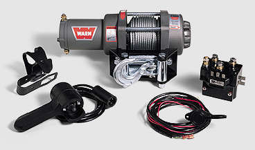
So I recently acquired for free a Warn A2500 that I'm planning on (multi) mounting to my trailer. It came with everything except the contactors (never heard that term until I looked up the parts list :eeek:)

Contactor:
63070.jpg


Will the control box/solenoids from a Warn M8000 work to function the ATV winch? I can't imagine the design being way different and the capacity shouldn't be a problem I wouldn't think...

After all, don't the separate solenoids (or one DPDT) just work to switch current flow depending on IN or OUT and thus would be same on all the winches...?
 
Well that's kinda what I was thinking. Just wasn't sure if there was some odd major difference in design between the large and smaller winches that I was missing. Thanks :beer:
 
Go down to your local ATV shop and see if they have any extra 'contactors' layin around----should be pretty cheap...Oh, and pick up a new 4x4quad while yer at it!!!!:redneck: (they'll likely give you a contactor if you do!) :D:D
 
Alright, I'm loosing my mind here...

So I picked up this control box for an M8000 for uber cheap and am really hoping I can make it work. But I'm currently stuck and not finding what I want online via searching. Here's my problem:

The A2500 has only two posts extending from the housing, marked 1 and 2. As such, the stock contactor only connects two wires to the winch (marked obviously 1 and 2).

A2500lgrV2.jpeg


Now the M8000 has 3 posts (marked F1, F2, and A) plus a ground screw. Thus the control box has a cable for pos batt terminal and then three other 2ga cables presumably for F1, F2, and A. (I have come to realize my control box lacks the 5th 10ga ground cable meant for the ground screw so I'll have to prolly wire that in myself)

My problem is, I can't seem to find it defined anywhere what F1, F2, and A (mostly A) actually DO! If I knew what A did, then maybe I could figure out my workaround...

superwinch_epi9_0_wiring_diagram.JPG


warn_Winch_wiring.jpg


Maybe this testing procedure will shed some light...?

warn_Winch_Motor_Test_Procedure.jpg


Maybe I need to study this one and I'm just too tired to wrap my mind around it right now.

schematic2.jpg


I just don't get why the A2500 runs on 2 posts (1 and 2) whereas the M8000 runs on 3 posts (F1, F2, A). I know my A2500 works both directions because it was tested by jumping straight to a battery, and sure enough polarity one way spooled in while polarity the other way spooled out.
 
So basically what I can take from the diagram is that:

OUT --> Positive Batt is sent to F1; meanwhile A is connected to F2
IN --> Positive Batt is sent to F2; meanwhile A is connected to F1


Now, how to retro fit this to 2 posts...
 
(A) has got to just be a ground doesn't it...? So if I ground (A), and run F1 to my 1 post and F2 to my 2 post I should achieve the same effect.


Last night I had tried to wire it in to that same effect without even realizing I was doing it, but it no worky. Now I'm thinking maybe the only reason it didn't work was because I'm missing that 5th smaller ground wire from the box which prolly just grounds the coils.

Hmmm....


BTW, if anyone sees something alarmingly wrong with my chain of conscience, by all means speak up so I don't fry myself and blow up the house :redneck:
 
I'm getting away from this thread it makes my brain hurt:haha:

I'm up way to late to be seeing wiring diagrams...

I am so glad my wife and son had mine installed so I didn't have to figure all this out....

Now I am leaving before my brain explodes all over my laptop...
 
So basically what I can take from the diagram is that:

OUT --> Positive Batt is sent to F1; meanwhile A is connected to F2
IN --> Positive Batt is sent to F2; meanwhile A is connected to F1


Now, how to retro fit this to 2 posts...


(I'm pretty sure this is right.... it's been several years since I went to school for this stuff)

The "A" terminal is the armature winding (part that spins). The F1 and F2 terminals are both sides of the field windings (part that doesn't spin). The field and armature windings are wired in series and the motor direction is changed by swapping the polarity on the field windings.

Look at the diagram at the bottom of the winch test proceedure. B+ is hooked to F2 and F1 is hooked to A. The other side of the armature winding is internally hooked to ground (B-). Current flows through the field winding, through the armature winding, and then to ground. To change the motor direction, F1 would be hooked to B+ and F2 would be hooked to A. Current flow is the same except that the polarity is swapped on the field.

Make any sense?

That small winch motor is probably a permanant magnet motor. Instead of using a field winding to create the magnetic field, permanant magnets are used instead. The armature is basically the same. To change rotation direction, the armature polarity is reversed. On that winch, I'd guess that the two terminals are connected to each end of the armature winding. Put B+ to one of them and B- to the other. To change direction, you swap the terminals.

There is a way you can get that controller to work with the PM motor. It'll take a bit of rewiring, though. I'll see if I can come up with a diagram...
 
Why don't you call up Warn and see how much they want for a new doodad.

Yeah, that's probably the best move.

Playing frankenstein with parts that aren't supposed to work together can be kinda fun, though. It can also be a fun way to let the smoke out of a perfectly good winch motor. :D
 
Why don't you call up Warn and see how much they want for a new doodad.


Already did. They wanted $60 plus s&h, and plus whatever a new female plug would cost. I was just hoping this would be a cheaper fix.


I think I may have found a different problem though. Sure enough none of the coils on the solenoids were grounded (I'm assuming they have to be like normal solenoids :eeek:). So I wired those into the good ground coming from the batt. Still nothing. So then I jumpered 12V power and ground to the coil solenoid posts which from my understanding should have opened the circuit and allowed current to flow through the high side posts, but the test light revealed nothing getting through. I tried pos and grnd on both coil posts just to be sure. So it's kinda seeming like the solenoids are toasted :booo:
 
It's working. :clappy::cheer::clappy::cheer:


I definitely needed to rewire those solenoid grounds. But loosening/tightening/wd-40ing all the different solenoid connections and controller connections seemed to do the trick. I just have the (A) wire plugged into the neg side of my quick disconnect so it grounds directly to the batt. And wired F1 to 1 and F2 to 2.


I'll let ya all know how long it lasts or if it blows up :redneck:


P.S. I knew if I kept that old 3 pin remote around for something, sooner or later it'd become handy :D
 
Dear NUZZY;
The most likely reason why the M-8000 has 3 posts and the 2500 has only 2 posts is because the M-8000 is a reversible motor, that is to say that is able to turn in two directions, whereas the A2500 motor most likely only spins in one direction. If the A2500 motor spins in two directions, then it most likely does so by switching the + and - polarity at the relay (what you call the contactor).

The terminal labeled *A* is the armature, *F1* is the Field winding and *F2* is also the same Field winding, only it's tapped into the Field winding at the other end of the Field from *F1*, which reverses the Field polarity, thus causing the motor to rotate in the opposite direction.
Your friend;
LAMAR
 
Top