• Help Support Hardline Crawlers :

Project scout

Today I cut off the sides of the Tubing at a 45 degree angle, and welded a plate on each end. I also put the finishing touches on my bushings as well as drill the angle Iron. Tomorrow I weld the angle to the tubing and weld the tubing to the frame.
 
p5020147.jpg

p5020146.jpg

p5020151.jpg

p5020145.jpg

p5020150.jpg

I also got all spring/shackle hangers welded off
p5020162.jpg

p5020160.jpg

p5020164.jpg

Running gear awaiting its service.....
p5020158.jpg

p5020154.jpg

p5020157.jpg
 
Last edited:
Well I have been working non stop the last couple days but I managed to get quite a bit done. I welded on some angle Iron to the crossmember and to the frame to add more strength.
p5060183.jpg

Also got the front axle on, the spindles and such on. Oh and tires! I am waiting on Ubolt plates for the rear. I also need to order wheel studs for it.
p5060181.jpg

p5060180.jpg

p5060179.jpg

Rear spring perches all tacked in place.
p5060185.jpg

p5060186z.jpg
 
Last edited:
The Scout rolls around my shop on its own weight now. I am waiting for some seals and stuff for the transfercase. Meanwhile I have been tearing into that. I'll get pics soon.
 
awesome build :awesomework:, i just semi finished my scout enough to go wheeling. Took it out to elbe this weekend, just to find out half way into mainline that my 727 tranny decided to go out! so now i gotta figure out wtf happened since it wont shift into gear. I have a front 60 waiting to be put in the front, and thinking about doing a rear 60, instead of a 14 bolt, i really dont like how huge and bulky the 14 bolts are, would rather get the 35 spline 60.

here are some pictures of my international

scout2.jpg


scout.jpg


IMG958060.jpg


:beer:
 
As of today the powerplant is in its place and I got it all bolted in. I was curious about the flex so I picked up the the tires and I got 27" in the front and 34" in the rear. I will get pics up tomorrow.
 
flex!
p8210107b.jpg

p8210108x.jpg

p8210106.jpg


Popped off the covers on the side of the transmission and found a 1/4 inch of rust and goo in the bottom. The transmission should be alot healthier now. While I was at it I figured I'd add some bling.
p7210073.jpg

p8210094.jpg


Clutch slave cylinder bracket.
p8210092.jpg

p8210095.jpg

p8210097.jpg
 
p9240115.jpg

p9240114.jpg

Body got in the way of the clutch, a little notch it fits perfect.
p9270135.jpg


The body is back on.
p9240113.jpg

p9240112.jpg

p9240118o.jpg


This is what happens then the front of the body slides off of the jackstands.. Yes, that is my valve cover. The body fell two feet before it did this. I am lucky this is all that is damaged.

p9240116v.jpg


Body is all back on just have to build new mounts. Also goin to have to do some trimming to my fenders!
p9270124.jpg

p9270123.jpg

p9270123.jpg

I am goin to need some fender flares. the tires stick out about 8 inches past the fender.
p9270122.jpg


Motor fits perfect
p9270129.jpg

Lots of room in the fire wall to mount junk.
p9270129.jpg
 
:haha: When I saw those first pics of the body jacked up on the frame my first thought was "that doesnt look safe".....then I scrolled down and..:fawkdancesmiley::fawkdancesmiley:
 
Your right, it wasnt safe...... look at my valve cover. :fawkdancesmiley:

This is how it started... Jackstands in fron t and single block in rear. Jackstands slipped off as i backed my forklift out.

unledxhg.jpg


unled2ttq.jpg
 
Last edited:
Well guys its been a while but I have been making progress I just havent been posting pictures because there wasn't much to post. Atleast nothing interesting.

First off rear brakes are on:
p1050065fs.jpg

I have been working on the clutch as well. The master cylinder is in and this is what I came up with as far as something goes to push the rod. Behind the triangle is 3/16 inch thick piece or steel that I welded strait up from the pedal and then I attached another piece from the side to make sure it wouldn't sway. I welded the triangle on because I figured it looked a little better and fancier than a --l shaped thing welded onto the pedal itself.
p1050061s.jpg


I also had to notch the floorboard for the clutch arm:
p1050067r.jpg


Has anyone else bought ScoutParts.com electric wiper conversion kit? In their instructions they said to cut out the back of your windshield frame so the motor can sit inside the frame of your windshield. So no problem right, I cut it out. Then I find that the hood nuts are also in there as well as the flat part that the hood hinges mount to. So somehow they expect the wiper motor to sit in there with about a 1/2 inch gap between the windshield frame itself and the actual body of the motor. Not to mention that your hinge bolt for the hood will ruin the motor if you thread it in to far. :flipoff: Not to worry I will come up with someway to mount it.
p1050062nt.jpg

p1050063g.jpg

I also made this sweet new bracket to mount the steering column. I do have to run one more brace to it still.
p1050064gm.jpg

I still need to trim my fenders there is not enough clearance between fender and the tires.
p1050069.jpg

This is the Rear.
p1050068f.jpg


I also got a Reid Racing Flat top knuckle, installed new ball joints and then put it on. I still need to order a steering arm.
p1050066l.jpg


http://img215.imageshack.us/img215/9810/p1050066l.jpg
 
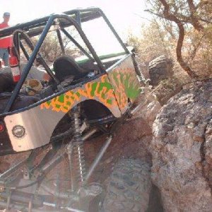
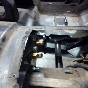
Well Yesterday I notched the floorboard for the exhaust. This is the only place that needed it.

p1130089r.jpg


And made a clutch stopper.
p1130090k.jpg


Here is a little bit of my own how to tech:

Well I am sure this applies to most IH vehicles that have a manual or maybe even a automatic transmission. The nylon bushings that they put in the pedal assembly will eventually wear out (if they havent already). I have come up with a permanent solution to the problem.

Remove the pedals from the pedal assembly and take out the old nylon bushings. If you have a manual you will need to remove the steel sleeve that is located to the left of the brake pedal at the top.

Once Everything is removed get a good 7/8 drill bit and clamp the pedal firmly to your drill press. In my case I used a vice. You need to drill down 3/4 of an inch into the tubing for the bushings to fit properly. The bushings that I bought were bronze The fit around the shaft that went through the top of the pedal and sleeve. They are 7/8 Outer Diameter, and 3/4 inch long.

After the hole is drilled tap the bronze bushing in with hammer and then grind off the excess on the outside. If the bushings are to tight use a dremel to take a little bit off the inside of the bushings. They should look something like this:

p1130081.jpg

p1130084u.jpg


The photo is a little blurry but I did leave a lip on one side to prevent side so side sway.

p1130079a.jpg


These are the old bushings I still have 2 remaining in my assembly. They are on the far outsides where I couldnt drill out without removing the pedal assembly. If you have a lathe you could turn down the bronze bushings a little to slide inside of there but I dont so I left 2 of the originals in there. Don't forget to grease the tubes before you reassemble everything.

p1130092v.jpg
 
So I had a slight problem I sold the factory radiator with my original IH motor. So I had to fab new mounts and I had a few radiators laying around but they were either to tall or too wide. So I got a Little crazy and came up with this. Sorry I didnt take a picture before I put it in

I cut out all of the Factory stuff Channel, metal, the X supports. So to replace the X supports I welded these in place. They are strips of metal that are about 2 inches wide and about 4inches or so tall. I would recommend that everyone do this because even before I started to get rid of the factory mounts I found the hood latch rather flimsy.
p3300020.jpg


This is a direct bolt in where the X supports used to be.
p3300018.jpg


p3300018.jpg


p3300019.jpg


Now for how I got the radiator to fit. You will notice its way wider than the radiator I left room to fit a bigger radiator in there if needed in the future.
p3300023.jpg

Inside the Fender:
p3300025.jpg

p3300024.jpg

p3300021e.jpg

p3300026.jpg


And here is the top mount:

p3300017.jpg
 
Alright this week I have been working with the steering column and the fan shroud. I took the steering column apart and got rid of the little button that you push down before it will let you turn the key back to off/lock position. I also Cut off about 4 inches of unnecessary plastic.

p4030046.jpg


I also made my self a steering wheel puller because I was too cheap to buy one. Only took about 10 minutes to make and it works great.
p4030045.jpg


Now for the fan shroud I cut the corners off at an angle and tig welded a piece of aluminum back in to patch the hole and then welded another piece on so that I have an L to mount it up with.

p4030047.jpg

p4030040l.jpg

p4030042m.jpg

p4030039.jpg
 
Well I haven't got a whole lot done in a while but I did get the steering column in and got this boxed in.

My lower steering column mount is merely a 2 1/4" exhaust clamp. A 2" would have been better I just didnt want to buy one.

p6040091.jpg

p6040090w.jpg

p6040096.jpg

p6040095.jpg

p6040094.jpg

p6040097.jpg
 
Top