You are using an out of date browser. It may not display this or other websites correctly.
You should upgrade or use an alternative browser.
You should upgrade or use an alternative browser.
Another lil something.....
- Thread starter crash2
- Start date

Help Support Hardline Crawlers:
crash2
-Oh no I picked a side-
crash2
-Oh no I picked a side-
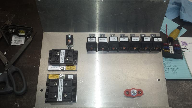
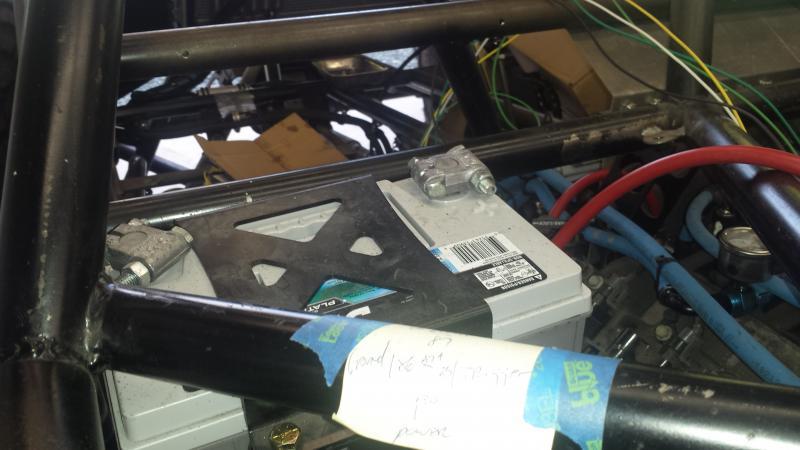
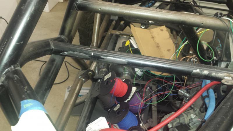
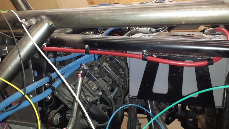
So since I had the electrical center in I wanted to start with the main power feeds. I threw the battery in and saw something I did not like. You can see the positive battery post "above" the tube line. If I turn the battery around the positive post is 1/4" away from the tube work. I had thought about when the hood gets built bump the sheet metal up.
Even that idea did not sound remotely safe---so poorly setup.
Even that idea did not sound remotely safe---so poorly setup.
Attachments
crash2
-Oh no I picked a side-
crash2
-Oh no I picked a side-
crash2
-Oh no I picked a side-
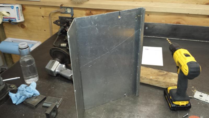
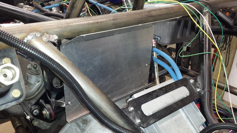
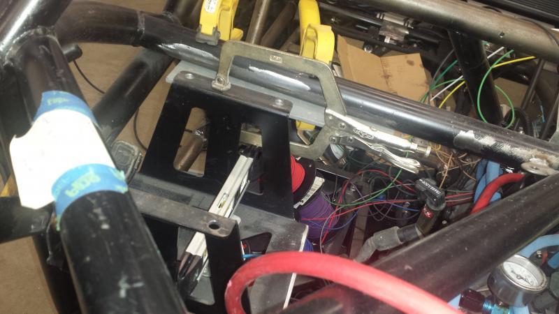
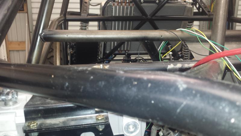
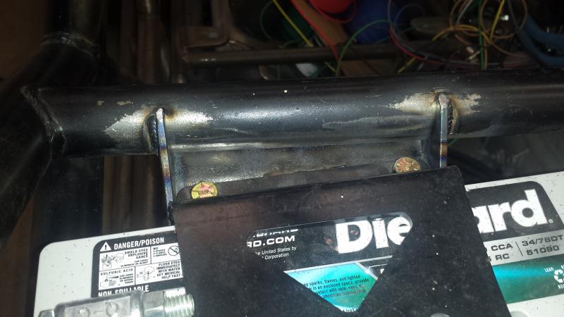
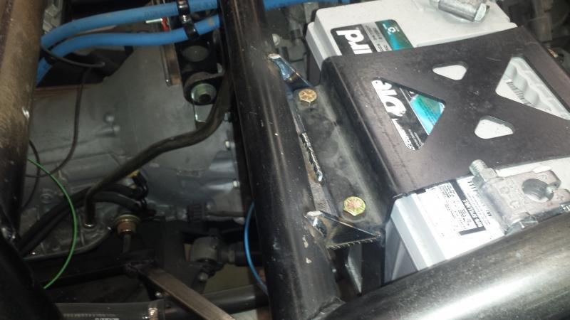
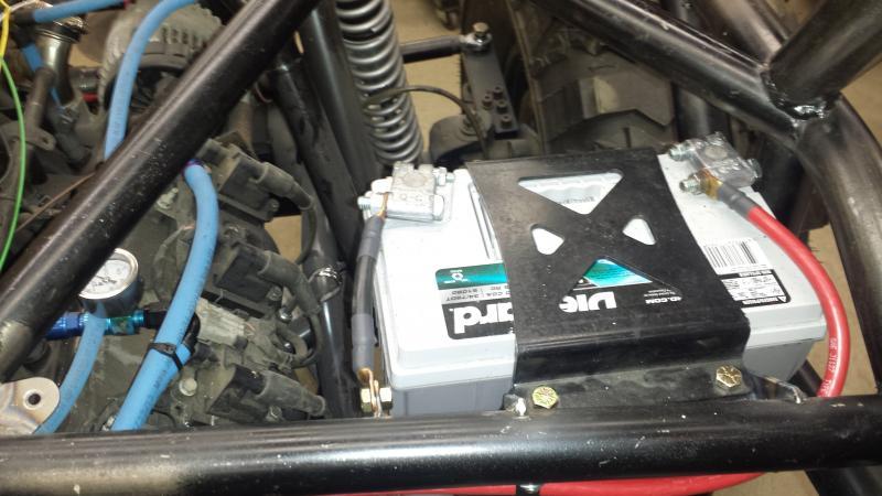
So the mount at the dashbar is MUCH beefier now. My intention with setting the battery tray up like I did was to also rotate the battery to make sure that positive post is well protected. As you can see everything is well below the tube line now.
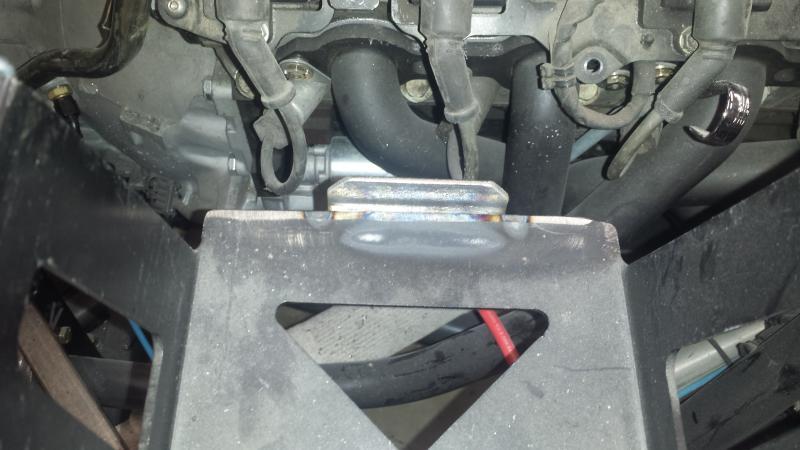
The end of the tray was also lopped off so the battery was not totally encased and could slide towards the motor. So I fixed that by adding some material...
The end of the tray was also lopped off so the battery was not totally encased and could slide towards the motor. So I fixed that by adding some material...
Attachments
Bobbo3234
Well-Known Member
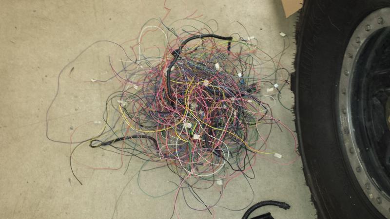
Pile of dead wire. There will be another pile about the same size from all the extra length that will be removed.
when you are shortening up wire are cutting a section out and then splicing? Or redoing the connection at a pin or device?
crash2
-Oh no I picked a side-
when you are shortening up wire are cutting a section out and then splicing? Or redoing the connection at a pin or device?
It depends on room and location. I have done it numerous ways.
crash2
-Oh no I picked a side-
crash2
-Oh no I picked a side-
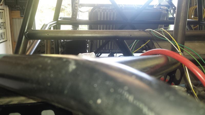
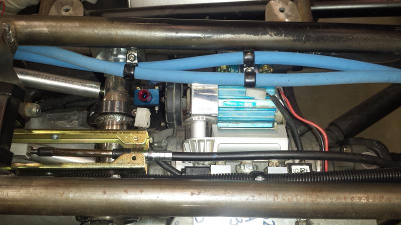
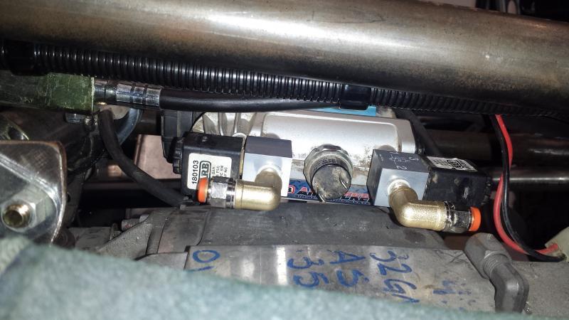
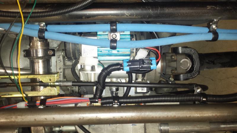
So this took some guess work and measuring to find a suitable location for the arb compressor. I had the mini and the normal to choose from and with lack of room I choose the smaller unit. After allot of thought I found the sweet spot for it down between the center chassis bars above the atlas. I had to redo a couple of the fuel line mounts and make a mount for the compressor and got it wired up.
Attachments
crash2
-Oh no I picked a side-
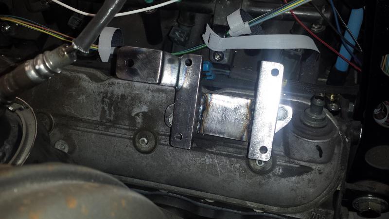
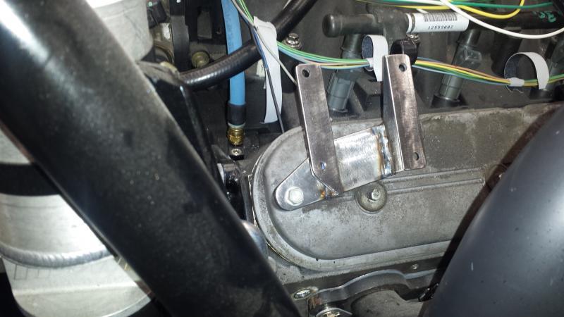
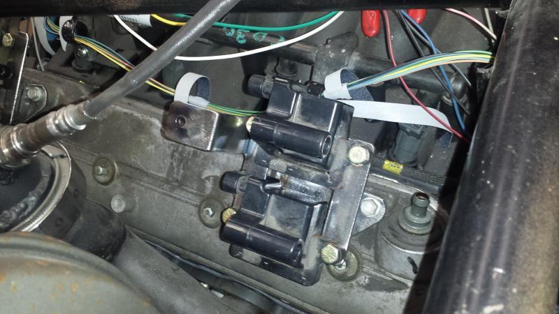
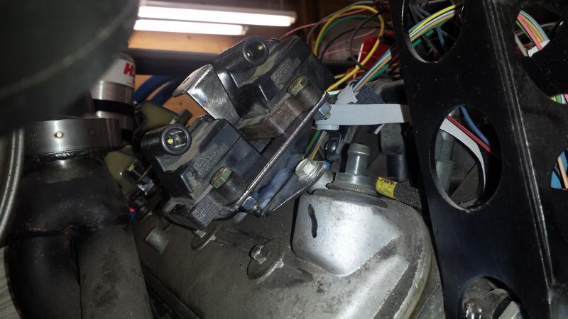
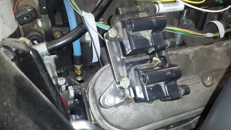
So before the wiring can get underway I had to resolve the driver side coil pack issue. Due to how the header is done the stock coil pack mount isn't even an option (I won't even say how it was mounted before :puke:).
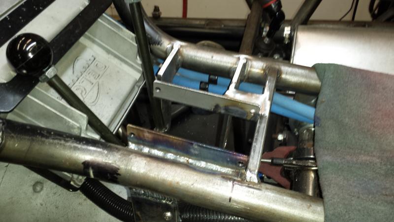
So I came up with these mounts and they should do the trick.
So I came up with these mounts and they should do the trick.
Attachments
crash2
-Oh no I picked a side-
crash2
-Oh no I picked a side-
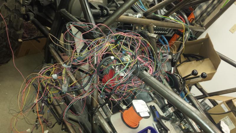
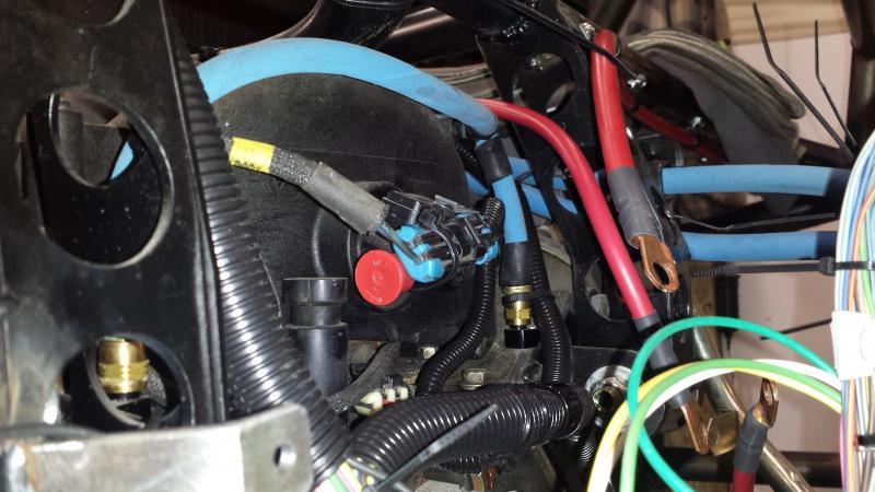
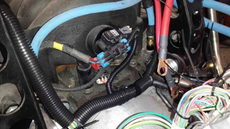
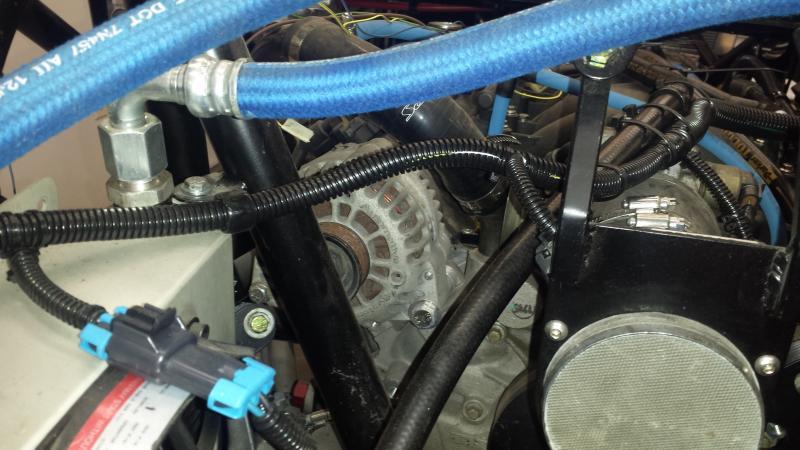
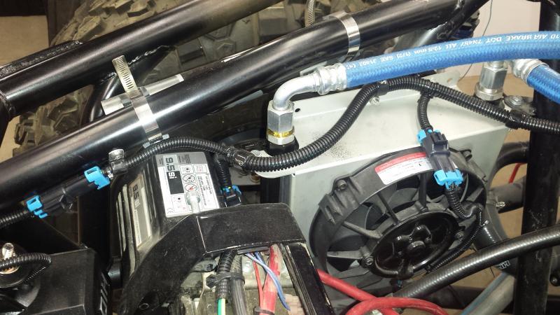
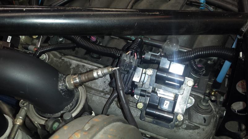
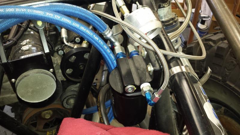
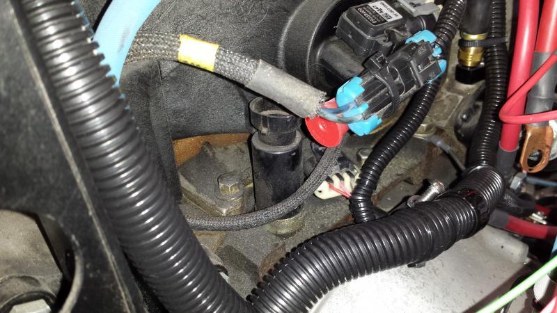
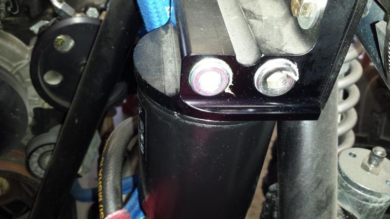
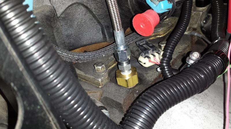
So I got the engine side of the wiring all redone--it fits MUCH better now..
Attachments
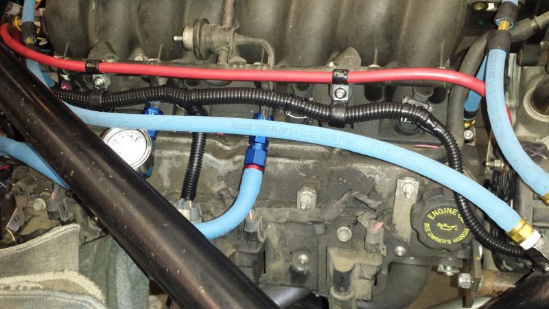
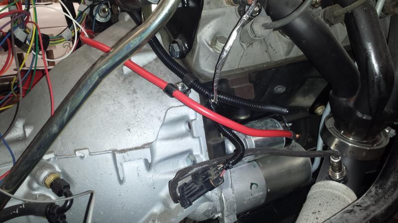
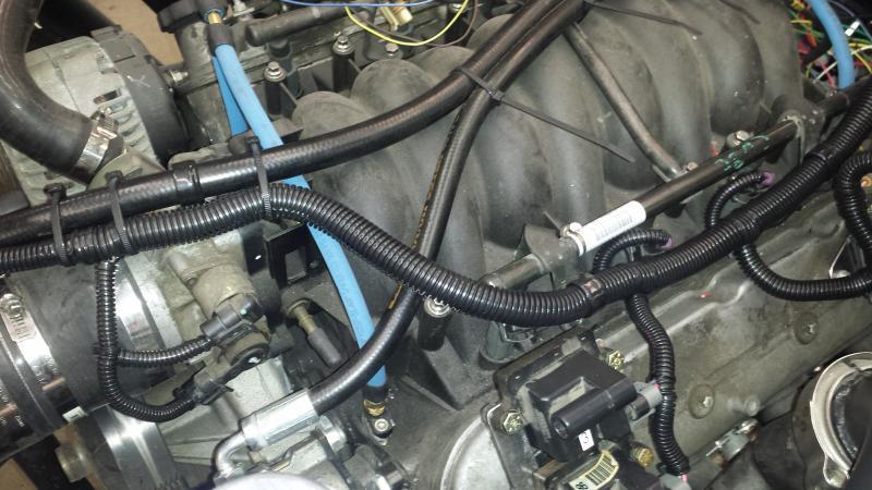
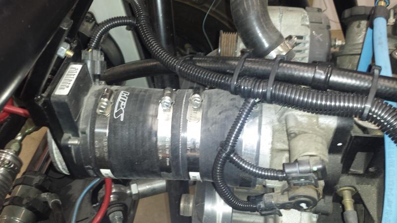
crash2
-Oh no I picked a side-
crash2
-Oh no I picked a side-
crash2
-Oh no I picked a side-
crash2
-Oh no I picked a side-
crash2
-Oh no I picked a side-
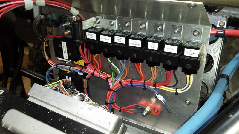
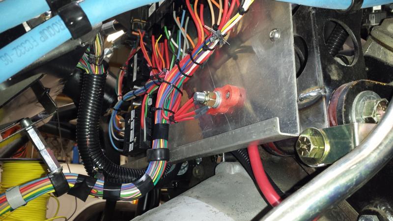
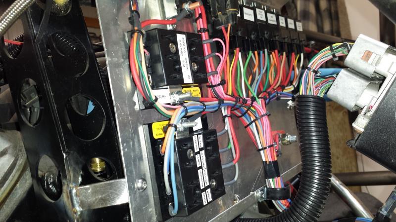
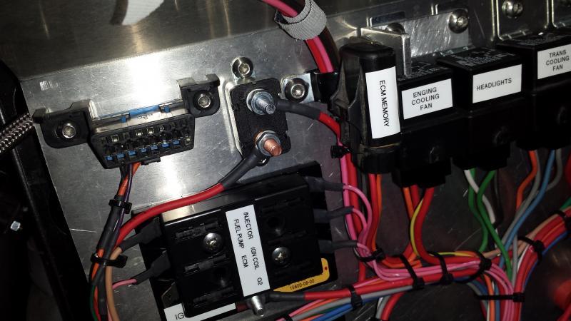
crash2
-Oh no I picked a side-
crash2
-Oh no I picked a side-
crash2
-Oh no I picked a side-
crash2
-Oh no I picked a side-
PORTER
Well-Known Member
Nice Mike, always have appreciated your attention to the little details.:cool:
crash2
-Oh no I picked a side-
My brain must work different--I just look at things differently and always see those small things.
thanks mike.
thanks mike.
crash2
-Oh no I picked a side-
crash2
-Oh no I picked a side-
crash2
-Oh no I picked a side-
crash2
-Oh no I picked a side-
crash2
-Oh no I picked a side-
crash2
-Oh no I picked a side-
Latest posts
-
-

-
-
-
-
-
-

-
-
-
For Sale First Generation 4Runner Rock Crawler for sale or trade
- Latest: FirstGenFunRunner
-
-
-
Withdrawn First Generation 4Runner Rock Crawler for sale or trade
- Latest: FirstGenFunRunner
-