crash2
-Oh no I picked a side-
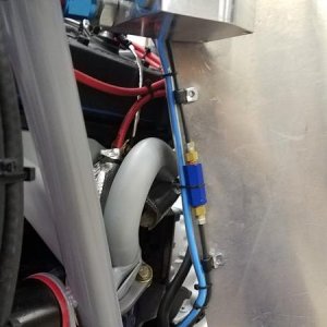
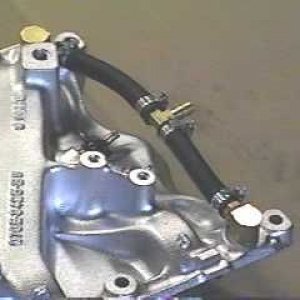
All I gotta do is figure out a connector for the temp sensor and we are golden.....:awesomework:


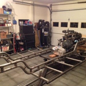
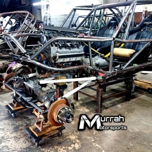
Nicest wiring harness ive ever seen in a toyota ,Good work Mike its coming along:awesomework:
 :thumbup::thumbup::thumbup::thumbup:
Only place that hasn't replied is the fitting place ....put in for the quote like 4 days ago ....guess they don't want my business
Western Fluids in Totem Lake may have the fittings you need on the shelf. I use them all the time at work.