Le sigh....
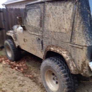
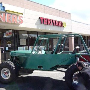
So I ended up with this 89 Bronco. It has a 77 F-150 axle under the front, coil springs and such. This axle, like other F-150 77-79 F-150 axles I've seen, has the classic horrible camber from the factory. Each side has about 1.5 degrees of positive camber. This is a stock axle, correct/stock knuckles (not a bastard combo), brand new spicer ball joints, and the housing is NOT bent. This is just the way it came, why they built them like this I do not know.
The problem is, it looks stupid... the camber is so postive that the tires are clearly in a V-shape (tops tilted out) when looking at the rig from various angles. The other, more pressing problem, is that it causes the tires to wear unevenly (more wear on the outside of the tire than inside), which is no small matter with big expensive 35's. And before you ask, the tire wear is NOT being caused by incorrectly set toe. The toe is dead on at 0.
So here's what I did... Moog makes an offset balljoint sleeve for the upper ball joint that adjusts either 1.5 degrees negative or 1.5 degrees positive on camber. Moog part #K936 which is a "best seller" according to Rock Auto, so obviously other people have this same problem. I ordered two, and proceeded to try to install them yesterday. They correct the perfect amount to put the camber right at 0, and all seems like it will work great, until...
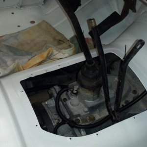
I got as far as bolting the spindle on before I realized that tilting the knuckle in 1.5 degrees makes the distance between the spindle and the tube-end on the housing too short, so that when you bolt the spindle down, it squeezes the axle shaft in and causes interference with rotation... once I tighten the spindle bolts down, the axle shaft locks up so tight I can't even rotate it with a prybar.
Anyone ever dealt with this before? What other options do I have and why is this such a stupid design? How can Moog sell this part when it obviously does not work as intended? Can I put my drill press to use and make a thin spacer to bolt between the caliper mount/spindle and the knuckle itself, as long as I don't make it too thick that the spindle doesn't seat in the knuckle anymore? Should I ditch it all and go back to a regular ball joint sleeve, and try to track down the angled spindle mount shims I couldn't find anywhere that are supposed to fix this problem? What is the RIGHT way to fix this apparent design flaw by Dana/Spicer?
Argh, that's my rant for the day. What a stupid, frustrating issue.
So I ended up with this 89 Bronco. It has a 77 F-150 axle under the front, coil springs and such. This axle, like other F-150 77-79 F-150 axles I've seen, has the classic horrible camber from the factory. Each side has about 1.5 degrees of positive camber. This is a stock axle, correct/stock knuckles (not a bastard combo), brand new spicer ball joints, and the housing is NOT bent. This is just the way it came, why they built them like this I do not know.
The problem is, it looks stupid... the camber is so postive that the tires are clearly in a V-shape (tops tilted out) when looking at the rig from various angles. The other, more pressing problem, is that it causes the tires to wear unevenly (more wear on the outside of the tire than inside), which is no small matter with big expensive 35's. And before you ask, the tire wear is NOT being caused by incorrectly set toe. The toe is dead on at 0.
So here's what I did... Moog makes an offset balljoint sleeve for the upper ball joint that adjusts either 1.5 degrees negative or 1.5 degrees positive on camber. Moog part #K936 which is a "best seller" according to Rock Auto, so obviously other people have this same problem. I ordered two, and proceeded to try to install them yesterday. They correct the perfect amount to put the camber right at 0, and all seems like it will work great, until...
I got as far as bolting the spindle on before I realized that tilting the knuckle in 1.5 degrees makes the distance between the spindle and the tube-end on the housing too short, so that when you bolt the spindle down, it squeezes the axle shaft in and causes interference with rotation... once I tighten the spindle bolts down, the axle shaft locks up so tight I can't even rotate it with a prybar.
Anyone ever dealt with this before? What other options do I have and why is this such a stupid design? How can Moog sell this part when it obviously does not work as intended? Can I put my drill press to use and make a thin spacer to bolt between the caliper mount/spindle and the knuckle itself, as long as I don't make it too thick that the spindle doesn't seat in the knuckle anymore? Should I ditch it all and go back to a regular ball joint sleeve, and try to track down the angled spindle mount shims I couldn't find anywhere that are supposed to fix this problem? What is the RIGHT way to fix this apparent design flaw by Dana/Spicer?
Argh, that's my rant for the day. What a stupid, frustrating issue.