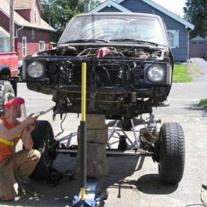
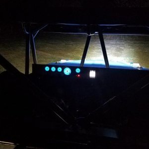
That pretty well sums up the engine swap. I apologize to all that actually read this far that it don't apply to but for the 2% that it may or will in the future I hope this helps!! I'm sure since its been nearly a year I have left out some small details but again read the threads I spoke of and they will hold the answers to any ?'s you should have! Also feel free to pm me (here on hardline) with any ?'s regarding this swap.Again I will say this is not a hard or difficult swap if you can simply read and apply and I would like to think anyone who wrote a thread regarding this swap that I stumbled upon because I would have never attempted it with out y'all's input! The only other thing I will give my opinion on is that I WOULD NOT attempt this swap without a complete donor vehicle. My opinion is that when I drove my crunched up taco in my building that I knew it would run and that obviously because of it running everything needed to make it run was right there in one spot! I'm sure you can source all the plugs,gas lines,harness's,etc,etc... From junk yards or worse yet dealers but the time,effort and money it would take would be horrible! Just saying my .02 cents worth anyways here are a couple of pics of the engine bay! Next up for this truck will be bobbing the rear of it.


 )
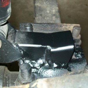
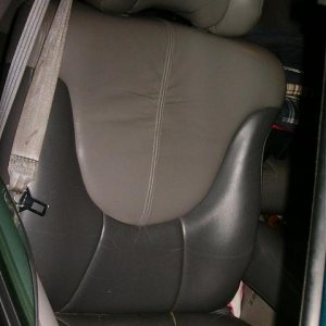
)  at this point I spent hours undoing tape, soldering and shrink wrapping one connection at a time! As mentioned before I wanted to have the obdll port for future diagnostic so I made it up at the ecu with an inline fuse to properly protect the ecu from defective scan tools( I guess this is why there fused from the factory) and decided I would just locate it behind the glove box since you don't need tools to get to it and it's out of the way of mud or debris! Also I had to figure out how to retain the ecu since the 3.4 brackets are completely different from the 22re brackets. After pondering on this I acheived this by bolting one of the 3.4 brackets on ,marking it to the length to be cut then cutting the mounting side of the 22re's bracket off and welding them together. This is the only bolt holding it in but as you can see in this pic ,it's tight up against the sheet metal stud in the floor that holds the back side of the plastic kick panel in place. This is because of the influx of wire behind it from all the extra wires it takes to complete the wiring. Anyways the kick panel will slide on to clear it making it a tight fit but helping secure it all the same! In the pic of the obdll plug you can see the kick panel is installed and that it does actually fit.