• Help Support Hardline Crawlers :

2rz-fe swap

crash2

-Oh no I picked a side-
Joined
Mar 26, 2001
Messages
39,839
Location
Da gold bar
So Rome's (seafarinman) 3.0 had finally started to go downhill and he had picked up a 2rz out of a 99 taco since the ouput of that series of motors was very impressive......

So he had dropped it off----FULLY loaded with lots of goodies (and I say fully loaded :haha: )

rome1.jpg


Look at that turd bucket :laughing3:

rome2.jpg


So I got the rig all unloaded and here is the new power plant :rockon:

rome3.jpg
 
I shudder in fear :haha: :haha: :haha:

rome4.jpg


Ahhhh--look at that---kinda makes ya wanna to get a 50 cal--and start blowing holes in stuff---big targets are fun :rofl:

rome5.jpg


Now were talkin :awesomework:

rome6.jpg
 
There is sits---mocking you--laughing at you----it wants to run over and kick you in the knee like a midget on goofballs :awesomework:

rome7.jpg


Ohhhh---goodies

rome8.jpg


Here is where I think we will run into problems with the header--it really dives pretty far from the motor and I am pretty sure by just looking that lil pesky frame rail is going to get into the way

rome9.jpg


rome10.jpg
 
So I went and slapped the new oil pan on

rome11.jpg


And what was with that new pickup tube--I made the old one fit with my 2lb mal---I dunno if it will work but it fit dag nabbit :p :rofl: :p


So once the new pan was on--it was time to start figuring out the wiring harness. On the last 2rz I did--I totaly ripped the harness apart--but I also had to 100% wire that rig up--this time I wanted to try and do it without modding the harness much--give it that true stock feel...

rome12.jpg


Well since we are using the stock guages--I went and swiped the stock oil presure and engine temp sensors off the 3.0. The temp sensor had to have the connector swapped where the oil pressure was the same..

rome13.jpg


rome14.jpg
 
So on the stock harness for the 3rz--the alt is simular to all the toy motors where the harness is seperate from the main harness. Well since there are a couple circuits that run thru the harness that are no longer needed and they just so happen to be near the starter---I went and tied the starter/alt wires into those circuits. So now the circuits are tied into the stock harness :awesomework:

rome15.jpg


Also on the stock harness--the map sensor was mounted on the driver fender well,, I went and modified the mount and now it sits on the back side of the intake..

rome16.jpg


So after some more reading--I had found this system actually doesn't use a map sensor--that sensor is for the evap system(fuel tank pressure) so I went ahead and removed it...
 
Well I decided to give the rig something---it needed some BLING that just jumps out and says----I am from gold bar :beer: :cheer:

rome17.jpg
 
Before I go and drop the motor in and start the motor mounts--I decided to go ahead and start tackling the engine bay..

rome18.jpg


First to go--the ABS crap--yup I just tied a rope to it--hooked it to my bumper and BAMMMMMO---that crap went a flying :haha:

rome19.jpg


Me and rome had talked about the A/C stuff--I sneezed and went a flyin---and it even landed in a nice organized pile :haha:
rome20.jpg


FInally starting to make a dent..

rome21.jpg
 
Rome you might wanna sit down for these next few pics--as they are disturbing and might send you into A) shock B) postal or C) OMG!!!:redneck:

Here is the new relay center--enough room for 9 relays--should be plenty :thumbup: Also you can see the main 12v junction. I am not 100% sure thats where its going to be mounted but pretty close to that...

rome22.jpg


I got the driver side fenderwell stripped of stuff--look at that room.

rome23.jpg


So now the driver side is all roughed in for the wiring--all non needed items stripped and the headlamp wiring (aftermarket) is now fully intergrated into the rig now. When I am done you won't be able to tell :awesomework:

rome24.jpg


The air compressor can now easily be removed. I re-sed that butt connector(forget the style) for the main power feed, and the ground/trigger have a sealed connector now

rome25.jpg
 
Here are the front lamps redone

rome26.jpg


The wiring goes thru the winch soloniod box and up the core support.

rome27.jpg


Here is the core support wiring done

rome28.jpg


rome29.jpg


And here is the start of the last portion of the reworking. I went and redid the power feeds in the relay/fuse box since toyota runs there alt feed wire thru those circuits since I do it how the domestics vehicles are done(much better setup and easier to diagnose if there is ever a problem).
Also I will be adding a fuse block in the passenger side under the dash all the smaller power feeds will run thru the firewall except the air pump(circuit breaker) and the cooling fan will have a large fusable link..

rome30.jpg
 
So before there were complete powers/grounds to the battery for both the jumper connector and winch. Experiacne has taught me thats a waiste and not needed--I prefer to keep systems simple--not only is there less used but easier to diagnose if there is ever a problem.

rome31.jpg


Before this hole was full of large wires--now its very simple--I added some protection for chaifing..

rome32.jpg


Here is the main battey feed wire from the front

rome33.jpg


Both battery cables are now done..

rome34.jpg


rome35.jpg
 
Here is where the new wire loom runs. I had a choice to either pop a new hole in the firewall--but opted not to since there was not much room around the large hole for the engine harness--and I didn't wanna run it thru the same hole as the engine harness... So I just decided to follow the other harness thru the fenderwell...

rome36.jpg


rome39.jpg


One thing that for some odd reason--drives me nuts(we can bounce back to how anal I am) is having wiring harness's popping out of the center of the firewall. So since all the power feeds and such for aftermarket goodies have been redone--and I knew I was going to be reworking those circuits in the dash--I went and pulled all the wires thru the firewall and rerouted the hood switch and alarm horn inot the new harness.

rome37.jpg


I also opted to reuse the bling fuse assemblies that rome had for both the inverter and amp. So they are wired to the fuses and I will finish those off when I am ready to dig into the dash..

rome38.jpg


It seems either I made a good mess of the band of midgets I have living in the corner of the shop got pissed at me and just destroyed all the work I just did :D

rome40.jpg
 
Ok--so the time for tossing the big items into the rig are getting closer but first I gotta get the trans back done. So time to throw the new gearset/input into the back case..

rome41.jpg


15 minutes later

rome42.jpg


The case and shift rails are clearanced for the new gearset.

rome43.jpg


All back together and ready to rock....

rome44.jpg


Here is the electric speed sensor Rome had gotten..

rome45.jpg


And here it is assembled on the stock speedo gear. A trick I found is to pull the driven gear out, screw the electric sensor onto the housing and then put the driven gear in while turning it..

rome46.jpg
 
So as I was getting ready to throw the back case on--something popped into my head--to check for shift rail interference between both cases--and sure enough there was an issue (got burned by it last time). So I measured and just had to remove material up to the line..

rome47.jpg


So I tossed the case case on, got the whole works onto the tranny jack and made sure the whole mess was 100% ready....

rome48.jpg


rome49.jpg
 
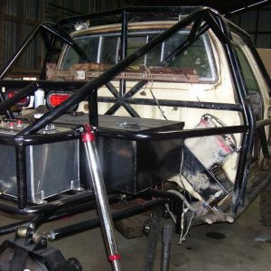
So that time finally came--- Got the engine hoist out and got the engine ready to raise. Well what a pain it was to get the motor just the right tilt without my good chain setup (sitting on another motor)..

So my plan is to get the motor dropped in(no clutch stuff to ease is joining the motor/tranny) and the tranny thrown in and bolted to gether so I can figure out where I want the motor/tranny to sit...

And wow---look its not a midget-- a dman ancle biting midget---but its something mocking you---------telling you to kiss off :D

rome50.jpg


Now here is where I was kinda shocked. Accoring to my research and measuring--there was no way the mounts would line up as far as the 4 bolt holes--but I will be god darn if they didn't line up with the motor roughly 3/4" from the firewall...

rome51.jpg


rome52.jpg


But the tilt of the mount is different as you can see by the second picture.

So I tossed the hood on real quick and the reservoir tank for the power steering is roughly 1/4" from the hood. But before looking at that I figured I needed to drop the motor roughly 3/4-1" due to clearance issues at the back of the motor..

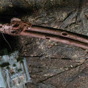
One thing I also wanted to check--was the clearance for the header since I didn't put the tilt of the motor into my earlier measurements.

Well here are my findings

rome53.jpg


rome54.jpg


The header was right against the bake lines--no biggy easily fixable--but the big issue as you can see in the second picture is it hits the frame---and its not a light tough against it either. Now if there was a 1" inward bend it would work perfectly :sad2:

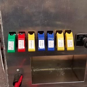
And here is my newest crossmember--pretty cool huh :rockon:

I tossed that on there so I could roll the rig back into the shop all the way.

So my next step is to remove the rear torque bar mounts since they are in the way for the new crossmember.

rome55.jpg


Once the crossmember is mounted I can go back to getting the motor where I want it...
 
Crash, whats the story on that 3.0? You think its worth swapping the heads I have on my rod knocking 3.0 onto it to get my 4Runner on the road?

As usual, your work looks amazing. Good job so far!

~T.J.
 
Top