• Help Support Hardline Crawlers :

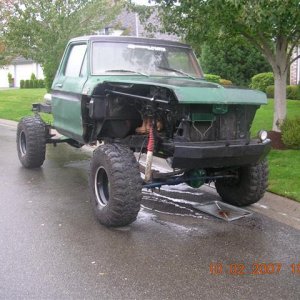
So i bought a 51 Whilly

actually it has none. it tells you to add grounds to all appliances, chassis to eng, eng to battery.... and to make sure they are not painted and shiny metal.

Huh strange. I don't know specifically about this one but if there's no ground wire then the sysyem must get ground through the body of the PCM. Is that grounded or does the harness instructions say anything about that?
 
Huh strange. I don't know specifically about this one but if there's no ground wire then the sysyem must get ground through the body of the PCM. Is that grounded or does the harness instructions say anything about that?

yeah the PCM is metal and mounted to metal, that was the check eng light staying on, as soon as i mounted the ecm that issue went away.

i remember the ground wire is less that stellar as i used the old one from the donor vehicle. i have other ground wires so i will make them clean and tight and check again. i will also replace the eng block to chassis as it is old and crumbly.

there was one wire for the harness i do not have hooked up as it made no sence. it was a wire that went to the brake switch? said it had to do with transmission control which should not be there? full manual trans.

ill clean grounds check again then call the tech line about the extra wire and the missing AC wire?
 
its not lack of goog ground:eeek: mbut i only had a few minutes to fawk with it.

my meter died so today i am taking the day off work (I lost a crown eating candy) meter is charged ill see what i can determine.
 
well meter on scope and i see no blip on the negative side of the coil wire.

calling the harness makers now.

They had me remove the piggyback chip they designed and try it and it still no worky.

according to them i should have it wired correctly....they are looking into something and will get back to me.:corn:
 
They sent me a bunch of stuff to check and i dont understand it. i think i need help, this crap is confusing me.

anyone who knows a chevy 4.3 CPI feel like spending some quality time over here?
 
They sent me a bunch of stuff to check and i dont understand it. i think i need help, this crap is confusing me.

anyone who knows a chevy 4.3 CPI feel like spending some quality time over here?

I don't have time and I'm not a "CPI" guy but maybe we could help you long distance- via the net?
What is it they sent you? Make sure it's not proprietary information before you post it..
 
its a check this, then check that... ive worked my way thru it untill it has me replacing my distributer DI module, thats where i left off today. i do have another.

i did have the wires to my coil kinda incorrect resulted in the same thing but not per the book so that is now corrected.

i have a friend who has one of these engines running in a blazer i am gonna ask them to come over next day i get to work on it.

maybe tomorrow afternoon as i have more dentist stuff.
 
Distributor Ignition System Check Chart (1 of 2)
41882962

Distributor Ignition System Check
41882961


Test Description:
Numbers below refer to circled numbers on the diagnostic chart.


  1. Two wires are checked, to ensure that an open is not present in a spark plug wire.
  2. A spark indicates the problem must be the distributor cap, rotor, or coil output wire.
  3. Normally, there should be battery voltage at the "C" and "+" terminals. Low voltage would indicate an open or a high resistance circuit from the distributor to the coil or ignition switch. If "C" terminal voltage was low, but "+" terminal voltage is 10 volts or more, circuit from "C" terminal to ignition coil or ignition coil primary winding is open.
  4. Checks for a shorted module or grounded circuit from the ignition coil to the module. The distributor module should be turned "OFF", so normal voltage should be about 12 volts. If the module is turned "ON", the voltage would be low, but above 1 volt. This could cause the ignition coil to fail from excessive heat. With an open ignition coil primary winding, a small amount of voltage will leak through the module from the "Batt" to the "tach" terminal.
Distributor Ignition System Check Chart (2 of 2)
41882963


Test Description:
Numbers below refer to circled numbers on the diagnostic chart.


  1. Applying a voltage (1.35 to 1.50 volts) to module terminal "P" should turn the module "ON" and the "tach" terminal voltage should drop to about 7-9 volts. This test will determine whether the module or coil is faulty or if the pick-up coil is not generating the proper signal to turn the module "ON". This test can be performed by using a DC test battery with a rating of 1.5 volts. (Such as AA, C or D cell). The battery must be a known good battery with a voltage of over 1.35 volts.
  2. This should turn "OFF" the module and cause a spark. If no spark occurs, the fault is most likely in the ignition coil because most module problems would have been found before this point in the procedure. A module tester (J 24642) could determine which is at fault.
 
naw it has two plugs:

one has two wires and goes from the coil to the dist.

the other has 4 wires and comes from the ecu...one of the four is the sprout. disconnect when setting timing.

hummm the stuff i posted last night i cant see from work?

now i can see it and this is not what i posted last night? i posted a diagram of the ingnition circut and reviewed the post...today it is a diagram of a heater circut....:eeek:
 
Last edited:
hummm the stuff i posted last night i cant see from work?

now i can see it and this is not what i posted last night? i posted a diagram of the ingnition circut and reviewed the post...today it is a diagram of a heater circut....:eeek:

Did you edit that post? Yeah it looks different to us also..

As for the test with the 1.5 volt batters I've never seen that one before but it looks easy to do. It would also be easy to swap in a spare ignition module and try it.
 
rick this is bugging me. not the lack of spark but the post change. this morning the diagrams of the dist circut were changed to heater box and duct work, now the dia is a picture of a 4 cylinder block with some bolts....

i just looked and now its a filter housing?

im gonna go have a few drinks......:beer:
 
Did you loose spark and injector pulse?


mike i am sending your crimpers back thru the NWW shuttle service...(KarlVP) thanks a million.

i havent checked injector pulse yet but i have no spark from the coil. i will be able to finnish checking the dist this afternoon after my dentist appt. this motor ran when pulled.

Fawkin dental benefits changed and they no longer cover any crowns.... gonna have to pay for it all myself. that hurts.

Possibly no KOH this year.:booo:

as for the pictures i posted its now a tranmission chart???

Check that---injector pulse will change how you diagnose it. If you look at any diagnosyics that are written correctly it states to check both spark and injection pulse.
 
Check that---injector pulse will change how you diagnose it. If you look at any diagnosyics that are written correctly it states to check both spark and injection pulse.


can i assume injector pulse and spark pulse come from the ecu ?

what kind of pulse should i see?

is it a 12V pulse or a ground pulse?

arent the injector pink wire hot at all times and the other is the pulse wire?

i have a great meter and can set to scope to read pulses but you need to know what to expect to set the scope parameters.

or can i just use a test light?
 
can i assume injector pulse and spark pulse come from the ecu ?

is it a 12V pulse or a ground pulse?

arent the injector pink wire hot at all times and the other is the pulse wire?

or can i just use a test light?

The ECM controls both and yes that's how it's wired. Just use a test light.
 

Latest posts

Top